Cc 101p • installation guide, Set the tone switch as desired (see – Extron Electronics CC 101P User Manual
Page 2
CC 101P
•
Installation Guide
4.
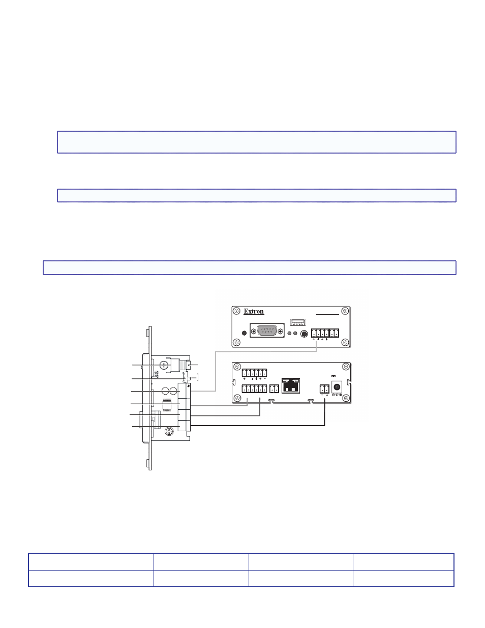
Connect the Line Output cable to the rear panel 3-pole captive screw connector (see
G
in figure 3), and to the Line Input on the front
panel of the CC 100C. Connect the positive (+) pole to positive (+) and the ground (arrow) to ground (arrow).
5.
Connect the Contact In cables to the rear panel 2-pole captive screw connectors (see
I
in figure 3), and to the relay connector on
the rear panel of the CC 100C. Connect the ”In” to the “NO” (normally open) and the ground “G” to common “C”.
6.
Connect the Contact Out cable to the rear panel 2-pole captive screw connector (see
H
in figure 3), and to the contact input
connector on the rear panel of the CC 100C. Connect the ”Out” to “0” and the ground “G” to ground “G”.
7.
Observing correct polarity (see Note), connect the power cable to the rear panel 2-pole captive screw connector (see
J
in figure 3),
and to the 2-pole power connector on the rear panel of the CC 100C.
NOTE: To maintain correct polarity, e
nsure the power cable is connected as positive (+) to positive (+), and negative (-) to
negative (-).
If the CC 100C is utilizing POE for power input, then either connect the CC 101P directly to an optional Extron power supply
(part number
70-775-01 12 VDC, 1.0 A, or part number 70-776-01 15 VDC, 0.8 A), or to the PoleVault Systems power supply,
observing correct polarity.
NOTE: The CC 101P is to be used with Extron power supplies only and as listed above
.
8.
Turn the system on and test the microphone transmission for level. Adjust the Mic Gain as needed (see
E
in figure 3).
9.
Set the tone switch as desired (see
F
in figure 3). When setting the switch to On (up), the unit emits a tone every 10 seconds
when the room is being monitored. Setting the switch to Off (down) disables the recurring tone (default setting).
10.
Mount the cabled device into the mud ring or wall box and attach the supplied Decora® faceplate.
NOTE:
To help complete installation and connections, see the CC 100C Installation Guide, available
.
RESET
RS-232/RS-485
REMOTE
STATUS
LINE
IN OUT SUB
CC 100C Front Panel
MIC
A B
USB
STORAGE
CC 100C
V
N/A
LAN/PoE
0 1 G NO C NC
POWER IN
12-15V
12W MAX
MIC SPKR
INPUT RELAY
CC 100C Rear Panel
On
Off
Adjust
Gain
Connect power cable here if CC 100C is NOT
using POE, otherwise connect direct to power supply.
CC 101P Side View
MI
C
GAIN
+
–
12-15
VDC
IN G
CONT
AC
TC
ON
TA
CT
OUT
G
+
–
LINE
O
UTPUT
J
E
F
G
H
I
Extron Headquarters
+1.800.633.9876 (Inside USA/Canada Only)
Extron Asia
+65.6383.4400
Extron China
+86.21.3760.1568
Extron Korea
+82.2.3444.1571
Extron Europe
+31.33.453.4040
Extron Japan
+81.3.3511.7655
Extron Middle East
+971.4.2991800
Extron India
+91.80.3055.3777
© 2014 Extron Electronics — All rights reserved. All trademarks mentioned are the property of their respective owners.
www.extron.com
2
Figure 3.
Wiring the Rear Panel of the CC101P to the CC 100C
68-2517-01
Rev A
05 14