Extron Electronics CC 101P User Manual
Preliminar y, Cc 101p • installation guide, Installation and cabling
Product Category
1
CC 101P • Installation Guide
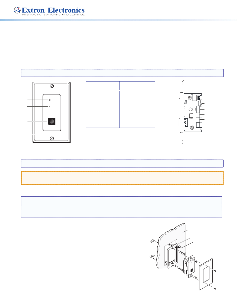
Extron CC 101P Campus Communication Panel is a wall plate accessory to the CC 100C Audio Codec and works with the Extron
GlobalViewer Campus Communication Suite (GVCCS) system. It fits in a single opening Decora style wall plate.
The front panel has a Call button, an integrated microphone, and a monitoring LED indicator. When the Call button is pressed and
released, the GVCCS operator is notified of an incoming call. The “MIC ON” LED indicator lights up when the GVCCS operator is
monitoring the room.
The CC 101P has two contact closures, and a mono balanced line level audio out on the rear panel that can be connected to the
CC 100C. A recessed microphone gain potentiometer on the rear panel is used to adjust the microphone gain.
NOTE:
Before installing this device, read the Extron Safety and Regulatory Compliances Guide
Installation and Cabling
NOTE:
The installation of this device must be done in accordance with National Electrical Wiring Codes.
ATTENTION: Do not install the CC 101P in a fire resistant rated wall or partition assembly.
ATTENTION: Ne pas installer le CC 101P dans un mur résistant au feu ou une cloison.
1.
Using the mud ring or a junction box as a guide, mark the edges and cut out the material within the marked area.
NOTES:
•
If installing a junction box, allow enough depth for the wall plate and cables, with consideration to the cable bend radius.
Do not bend the cables at 90 degrees.
•
Conduit and conduit adapters should be used.
2.
Either:
z
Insert the mud ring into the opening, rotate the locking arms, and
secure
with the supplied screws,
or
z
Insert the wall box and secure with nails or screws.
3.
Run the power, contact in and contact out cables, and the line out cables
from the PoleVault switcher location, going behind the wall and to the
CC 101P location, then thread the cables through the mud ring or wall box
Rear Panel Connections
MIC ON
Extron
CALL
D
C
A
B
E
F
G
H
I
J
MI
C
GAIN
+
–
12-15
VDC
IN G
CONT
AC
T
CONT
AC
T
OUT
G
+
–
LINE
O
UTPUT
Front Panel
Features
Rear Panel
Connectors
A
Mic On LED
B
Microphone
C
Call button
D
Decora Faceplate
E
Mic Gain
F
Tone switch
G
Line Output
H
Contact Out
I
Contact In
J
Power
Decora
Faceplate
Extron
CC 101 P
Wall
Mud Ring
Cabling
MIC
ON
Ex
tron
CA
LL
Figure 1.
CC 101P Front and Rear Panel Features
Figure 2.
Installing the CC 101P in the Mud Ring
PRELIMINAR
Y