Cable cubby • setup guide (continued), Preparing the table, Preparing the cable cubby – Extron Electronics Cable Cubby Setup Guide User Manual
Page 2: Warning, Attention, Tips
2
Preparing the Table
WARNING:
Wear safety glasses when cutting the hole in the table. Failure to comply may result in eye injury.
ATTENTION
: • The opening in the table for the Cable Cubby should be cut only by licensed and bonded craftspeople.
• Exercise care to prevent scarring or damaging the furniture.
•
Cable Cubby 300 installation — Ensure that the table surface is at least 5/8 inch (0.625") (15.88 mm) thick.
• Cable Cubby 600/800 installation — Ensure that the table surface is at least 3/4 inch (0.75") (19.05 mm) thick.
Cut a hole in the surface where the enclosure will be installed. There are three methods for cutting the hole in the table:
z
A hand router and the appropriate Extron Cable Cubby routing template.
HSA 200
USER A
CCESS
HSA 200
CABLE CUBBY 300
CABLE CUBBY 300
USER A
CCESS
See the table below for part numbers. See the HSA Series and Cable Cubby
Routing Template User Guide, available on the Extron website,
www.extron.com
,
to prepare the template and use the template to cut the hole.
NOTE:
The metal routing template is reusable. Do not discard this
routing template when the installation is complete.
z
A CNC wood router and the exact cut-out dimensions for your model. See the
table below for cut-out dimensions:
z
A jigsaw and a paper cut-out template (available on the Extron website,
www.extron.com
)
NOTE:
The underlined dimension in the table below is the side on which
the lid opens.
Routing Template
Part Number
Cut-out Dimensions
Product
Width
Depth
Cable Cubby 300S
70-237-01
4.65 inches (11.81 cm)
6.00 inches (15.24 cm)
Cable Cubby 300C
70-237-01
6.03 inches (15.32 cm) diameter
Cable Cubby 600
70-239-01
6.49 inches (16.48 cm)
6.49 inches (16.48 cm)
Cable Cubby 800
70-240-01
7.89 inches (20.04 cm)
6.35 inches (16.13 cm)
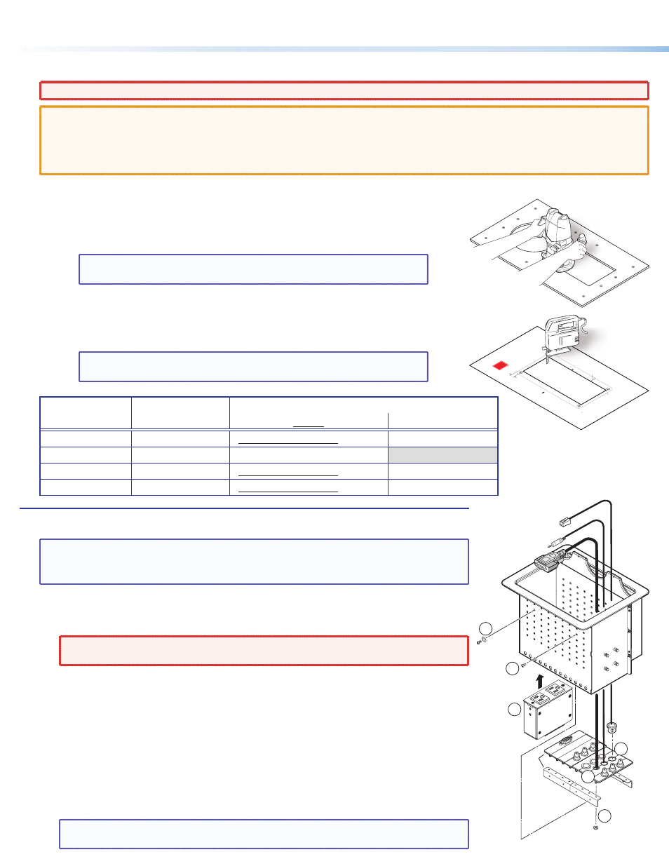
Preparing the Cable Cubby
TIPS:
• Install any power modules before installing AAPs.
• Populate the shelf brackets with cables and AAPs outside the enclosure and then
install the populated AAP shelf assembly into the enclosure.
Install the power module and cables in the pass-through holes as follows:
1.
Gently push any power modules into the desired position and elevation. Secure the
modules into position with the provided screws and washers.
WARNING:
To ensure good electrical grounding, use the star washers with the
screws.
2.
Rest the cables in the half-moon cutouts of two cable pass-through AAP segments (
Ç
)
and secure the next cable pass-through AAP segment to the shelf brackets with the
provided #4-40 nuts (
É
).
3.
Repeat step 2 for the remaining cables and cable pass-through AAP segments.
4.
Snap the appropriate size split grommet over each cable and into the pass-through holes
with the flange of the grommet on top.
5.
Snap the included hole plugs into unused hole.
6.
Gently push the AAP shelf assembly into the enclosure at the desired elevation.
Ensure there is enough space above the AAP assembly for the Cable Cubby lid to close
completely. Secure the AAP shelf assembly into position with the provided screws.
TIP:
If the AAP shelf assembly does not slide easily into the cubby, loosen the AAP
mounting nuts. Retighten the nuts once the AAP shelf assembly is installed.
User Access
Cut-Out
Template f
or Extron's
Cable Cubb
y 200
.350" (0.90 cm
)
Print this
template
at 100%
Trim Ring
Lip
Trim Ring’
s Outer Edge
0.00”
(0.00 cm)
0.02 (0.05 cm)
+
1. Confirm Pr
oduct to be installe
d
2. Measure cutout and template
3. Af
ter
ch
ecking,
cut opening
e
g
1
1
6
2b
4
2a
Cable Cubby 800
Shelf
Bracket
AAP
Shelf
Assy.
Cable Cubby • Setup Guide (Continued)