Extron Electronics CAT 5 Receivers User Manual
Page 7
CAT 5 Receivers • Installation and Operation
CAT 5 Receivers • Installation and Operation
Installation and Operation, cont’d
2-3
Installation overview
To install and set up a CAT 5 receiver and the associated CAT 5
transmitter(s) for operation, perform the following steps:
1
Disconnect power from all of the equipment, including the
video source(s) (such as computers or DVD players), the
transmitter, the receiver, and the output display(s).
2
For component, S-video, or composite video, ensure that
the internal jumpers are in the correct position (all except
CAT 5 R AV). See Jumpers in this chapter.
3
Mount the receiver in a rack (CAT 5 R BNC A or
CAT 5 R BNC AV only), under a desk or podium, in a desk
or table, or on a projector bracket. See the instructions that
accompanied the mounting kit for specific information.
4
Connect the cable(s) between the CAT 5 transmitter(s) and
the receiver. See Transmitted signal cabling in this chapter
and refer to the CAT 5 Transmitter Family User’s Manual,
part #68-546-01.
5
Connect the output cables. See Output cabling in this
chapter.
6
Configure the CAT 5 transmitter(s). Refer to the CAT 5
Transmitter Family User’s Manual, part #68-546-01.
7
Connect power cords to the CAT 5 receiver, the CAT 5
transmitter, and turn on the video source(s) and the
output display(s).
All CAT 5 transmitters include a 15V external power
supply. The transmitters also receive power from the
associated Extron CAT 5 receiver(s) via the CAT 5 cable.
Extron recommends using the local power supply;
however the power supply may not be necessary in some
applications. Use the following guidelines:
•
The CAT 5 T 15HD A, CAT 5 T 15HD AV, and
CAT 5 T BNC may not require a local power supply
for cable lengths of 300 feet or less.
•
The CAT 5 T AV may not require a local power
supply for cable lengths of 800 feet or less.
•
The CAT 5 T BNC DA4 always requires the local
power supply.
If problems are encountered, use the local power supply.
8
Adjust the picture controls on the front panel of the
transmitter(s) and receiver. See Front Panel Controls and
2-2
Indicators in this chapter and refer to the CAT 5 Transmitter
Family User’s Manual, part #68-546-01.
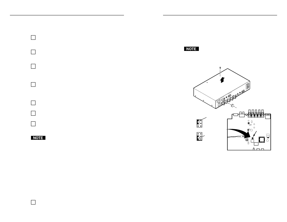
Jumpers
The RGB video receivers can be configured to receive
component video, S-video, or composite video.
The receivers are factory configured for RGB video. To
receive any other type of video, reconfigure the jumpers.
1
.
Remove the three screws on each side and the two screws
on top of the cover (figure 2-1).
RGB
PC board (inside case)
CAT 5 T BNC and CAT 5 BNC DA4
J3
1
2
3
J3
U25
Component,
S-video,
composite
J3
1
2
3
J3
RG
B
OU
TP
UT
RG
B
IN
PU
T
A-
V
IN
PU
T
A-
V
OU
TP
UT
AU
DI
O
R
VI
DE
O
G
B
H/
HV
V
A
AU
DI
O
L
R
B
A
L
R
B
ISOG
C SYNC
50
/60
H
z
10
0-2
40
V
1.
3A
Lift Cover
straight up
CAT 5 R BNC AV
Remove (8)
Screws
Figure 2-1 — Jumper configuration
2
.
Using an Extron BNC extraction tool (part #100-096-01) or a
9/16”, deep well socket with thin walls, remove the five or
six hex nuts securing the BNC connectors to the rear panel.
3
.
Slide the cover forward until the cover clears the BNC
connectors and then lift the cover off.
4
.
CAT 5 R BNC AV only
: Remove the four screws securing
the video board to the RGB board and lift the video board
out of the way.
5
.
Locate J3 on the RGB video printed circuit board.
Installation