Installation and operation, cont’d, Front panel controls and indicators, Power connector – Extron Electronics CAT 5 Receivers User Manual
Page 10
CAT 5 Receivers • Installation and Operation
CAT 5 Receivers • Installation and Operation
Installation and Operation, cont’d
2-8
R
-or-
-or-
G
B
H/HV
V
The H/HV and V BNCs only output sync, not video,
signals.
4
DIP switches
SOG switch
— Set this rear panel switch up for RGsB
video and down for RGBHV or RGBS video.
C Sync switch —
Set this rear panel switch up for RGBS
video and down for RGBHV or RGsB video.
Set both DIP switches down for RGBHV video.
Composite video
The CAT 5 R BNC AV and the CAT 5 R AV receive and output
composite video.
5
Video connector
— Connect a composite video device to this
rear panel BNC connector. Digital audio can also be connected
to this connector.
Audio
All Extron CAT 5 receivers receive and output stereo audio. The
receivers output the audio on both left and right RCA
connectors and on 3.5 mm, 5-pole captive screw connectors.
6
Stereo audio output connectors
— Connect left and right stereo
audio cables between these rear panel RCA connectors and the
output device’s stereo audio inputs.
Only analog, line level, unbalanced audio signals can be
output on these connectors.
7
Stereo audio 5-pole captive screw connector
— Connect audio
devices, such as an audio amplifier or powered speakers, to
these connectors. These 3.5 mm, 5-pole captive screw
connectors output unamplified, line level audio. Figure 2-5
shows how to properly wire an output connector.
Unbalanced Output
Tip
See warning
Sleeve
Tip
See warning
Balanced Output
Tip
Ring
Sleeve (s)
Tip
Ring
Figure 2-5 — Audio output captive screw connector
wiring
Connect the sleeve to ground (Gnd). Connecting
the sleeve to a negative (-) terminal will damage the
audio output circuits.
If only an audio signal, no video, is received, connect a
ground wire between the chassis ground and an earth
ground in the equipment rack or other grounded device.
If the receiver is not grounded, a crackling sound may be
heard in the audio output.
Power connector
8
Power
CAT 5 R BNC AV —
Plug a standard IEC power cord into
this connector to connect the CAT 5 R BNC AV to a
100 to 240VAC, 50 Hz or 60 Hz power source.
If the remote power distance is too great to power the
transmitter, the video image is missing, distorted, or
noisy, or the receiver’s Manual/Auto LED flashes. The
transmitter requires a local 15V power supply.
CAT 5 R BNC AV and CAT 5 R AV —
Plug the external
15V power supply into this captive screw connector.
The power supply is included with both units.
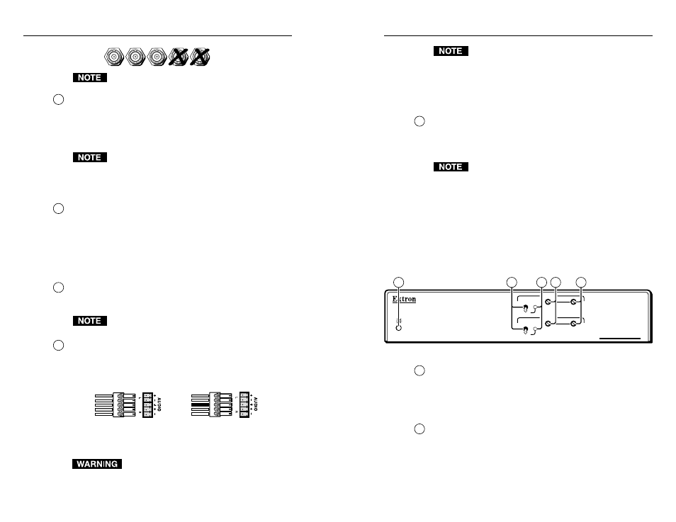
Front Panel Controls and Indicators
All of the CAT 5 receivers have similar controls and indicators
(figure 2-6).
CAT5 R BNC AV
VIDEO
MANUAL
AUTO
LEVEL
PEAKING
RGB
MANUAL
AUTO
LEVEL
PEAKING
1
2
3
4
5
Figure 2-6 — Control and indicators
1
Power indicator
Amber —
indicates that power is applied, but that the
transmitter is not connected to a receiver.
Green —
indicates that a transmitter is connected to the
receiver.
2
Manual/Auto switch
— With this switch in the Auto position,
the receiver automatically adjusts the level and peaking to
compensate for long cable runs. In the Manual position, you
can manually compensate for long cable runs using the level
and peaking controls.
2-9