2 electrical installation, 1 power supply connection, 2 i/o connection – Xylem ECOCIRC XL, XLplus Electronic drive User Manual
Page 4: 3 wiring harness
2 Electrical installation
Power Supply: 1 x 230V ±10%, 50/60Hz
Check that the power supply line is provided with:
A mains isolator switch with a contact gap of at
least 3mm
A high-sensitivity (HS) 30mA differential switch
(RCD
– Residual Current Device), suitable for
earth fault currents with DC or pulsating DC
content
(preferably
Type
B).
If an automatic circuit breaker (CB) is required,
use an automatic circuit breaker with C-type
characteristic curve.
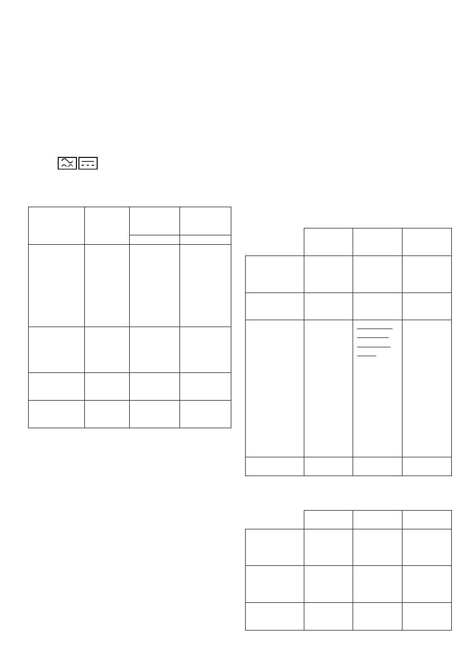
ecocirc XL /
XLplus
Voltage
rating
Nominal
max input
current
Recommen
ded line
protection
[A]
[A]
25-80
25-100
32-80
32-100
40-80
40-100
50-100
36-45
15-75
1
230V
50/60Hz
<2
3
32-120
40-120
50-80
65-80
55-45
1
230V
50/60Hz
<3
4
50-120
65-120
65-130
1
230V
50/60Hz
<5
6
80-120
100-120
70-145
1
230V
50/60Hz
<9
10
Table 1
2.1 Power Supply connection
For plug-connected models, see
the subsequent steps:
1. Open the connector cover and insert the cable
inside the cable gland
2. Pull down the contact retention spring
3. Connect the cable according to the wiring diagram
4. Align the two parts of the connector
5. Push the two parts one inside the other
6. Close the connector and tight carefully the cable
gland
For terminal-connected models, see
follow the subsequent steps:
1. Open the terminal block cover removing the
screws
2. Insert the cable inside the M20 cable gland
3. Connect the cable according to the wiring diagram
a. Connect the ground (earth) lead; be sure
that the ground (earth) lead is longer than
the phase leads
b. Connect the phase leads
For cable requirements and organization of wiring
harness inside the cable glands, refer to par.
2.2 I/O connection
1. Open the terminal block removing the screws
2. Connect the appropriate cable according to the
the requirements of par.
and
2.3 Wiring harness
For plug-connected models
Plug
connector
M12 (1)
Cable Ш
2ч5mm
M12 (2)
Cable Ш
2ч5mm
Power supply
3x
0.75÷1.5
mm
2
(2P+T)
Fault signal
2x
0.75÷1.5
mm
2
- Analog 0-
10V
- External
pressure
sensor
- External
temperature
sensor
- External
start/stop
If NO fault
signal on
this cable
gland.
Multi-wire
control
cable,
number of
wires
according
to number
of control
circuits.
Shielded if
necessary
Multi-wire
control
cable,
number of
wires
according
to number
of control
circuits.
Shielded if
necessary
Communicati
on bus
Bus cable
Table 2
For terminal-connected models
M20 Cable
Ш 5ч13mm
M16 (1)
M16 (2)
Power supply
3x
0.75÷2.5
mm
2
(2P+T)
- Power
supply
- Fault signal
5x
0.75÷1.5
mm
2
(4P+T)
Fault signal
2x
0.75÷1.5
mm
2