Bell & Gossett HFT Expansion Tanks for Hydronic Heating Systems User Manual
Page 3
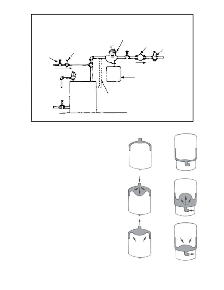
Figure 2
B&G Flow
Control Valve
To System
B&G Booster
Air Separator
B&G Pressure
Reducing Valve
Shut Off Valve
B&G Relief
Valve
C.W. Fill
Flow
Return
Boiler
Optional Side
Outlet Boiler
Connection
Diaphragm Type Expansion
Tank “HFT”
OPERATING INSTRUCTIONS
1. The expansion tank is typically installed in the bottom
of an air separator. Its sealed-in air pre-charge prevents
water from entering the tank until the system pressure
exceeds the pre-charge pressure
2. As the water temperature rises, expanded water enters
the expansion tank’s water reservoir. The pre-charge air
chamber absorbs the pressure increase, keeping system
pressures below the relief valve setting.
3. As water temperature decreases the pressure in the
air chamber forces water back into the system until the
expansion tank is empty.
The selection, application, installation and servicing of
this product should be performed by a qualified
professional within all applicable safety and code
requirements.
Air
Cushion
Air
Cushion
Air
Cushion
Air
Cushion
Air
Cushion
Air
Cushion
Models HFT-15
thru HFT-90
Models HFT-30V
thru HFT-160V