Appendix c – Bell & Gossett S14141B 70X Multiple Pump Pressure Booster Systems User Manual
Page 10
10
APPENDIX C
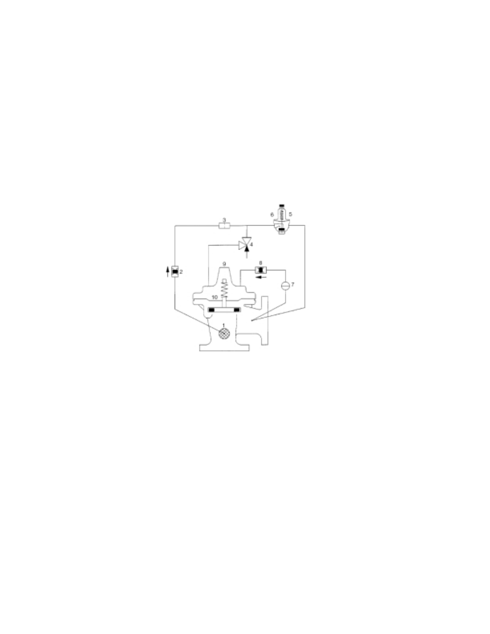
PROCEDURE FOR FIELD BALANCING PRESSURE REDUCING VALVE
COMBINATION PRESSURE REDUCING AND CHECK VALVE
Item
Name
Primary Function
1
Strainer
Prevents orifice from clogging
2
Check Valve
Prevents backflow from top of diaphragm when pumping stops.
3
Orifice
Provides metered water flow to top-side of diaphragm.
4
Opening Speed Flow Control
Dampens pressure fluctuations (slow opening).
5
CRD
Pilot PRV.
6
Gauge
Optional location for system pressure gauge.
7
Cock
Adjustment for rate of closure (non-slam).
8
Check Valve
Prevents backflow from top of diapgragm during normal operation.
9
Vent
Bleeds air from top of diaphragm.
10
Diaphragm
Divides inlet and outlet pressures.
Figure 2
1.0 Pressure Reducing valve (PRV) Adjustment
1.1
The pressure reducing valves are "factory set". If
needed, the following items should be checked
first before any attempt is made to change the
setting:
a) Does the desired system pressure correspond
to the pressure indicated on the nameplate?
b) Is the suction pressure equal to or higher than
the pressure indicated on the nameplate?
c) Is the demand (GPM) within the capacity indi-
cated on the nameplate?
d) Has the PRV been properly vented?
1.2
Any deviation from the above conditions will pre-
vent the unit from operating at the factory (name-
plate) settings.
1.3
To adjust the PRV place the pump in manual oper-
ation per Technologic 500X instruction manual.
With the pump now running, slowly close the main
gate valve downstream of the discharge header
allowing a trickle of water to flow through it. Read
the system pressure on the display. It should read
3 or 4 psi higher than the desired system pres-
sure. If not, remove the protective cap on the pilot
control valve and loosen the jam nut on the
adjusting stem of the PRV. Slowly turn the stem
clockwise to increase the delivery pressure and
counter clockwise to decrease pressure. (Note
that a pilot valve furnished for a 20 to 300 psi
range will change the main valve setting approxi-
mately 28 psi for each full turn of the adjusting
screw.) Set the screw so the system display reads
3 to 4 psi higher than the desired system pressure.
1.4
Open the gate valve fully. If feasible, draw be-
tween 50 to 80% of the designed pump capacity
to recheck valve setting. The display should now
read the desired system pressure. Tighten jam
nut and replace cap.
1.5
Repeat the above procedure for all pump and
valve combinations as required.
1.6
The CV Flow Control Valve (opening speed con-
trol) may require field adjustment if pressure hunt-
ing occurs. Normal setting of the valve is from 4 to
7 turns open. Never open more than 8 turns.