3 electrical connections – Xylem CL500 ONLINE CHLORINE ANALYZERS User Manual
Page 12
The fluid waste from drain connection of this instrument contains reagents
diluted with large quantities of sample water. Global Water Instrumentation
recommends that operators check with local authorities concerning proper
disposal of waste fluids.
A ½ “ ID tubing can be placed over the cabinet vent to redirect accidental
spills of reagent to a suitable container.
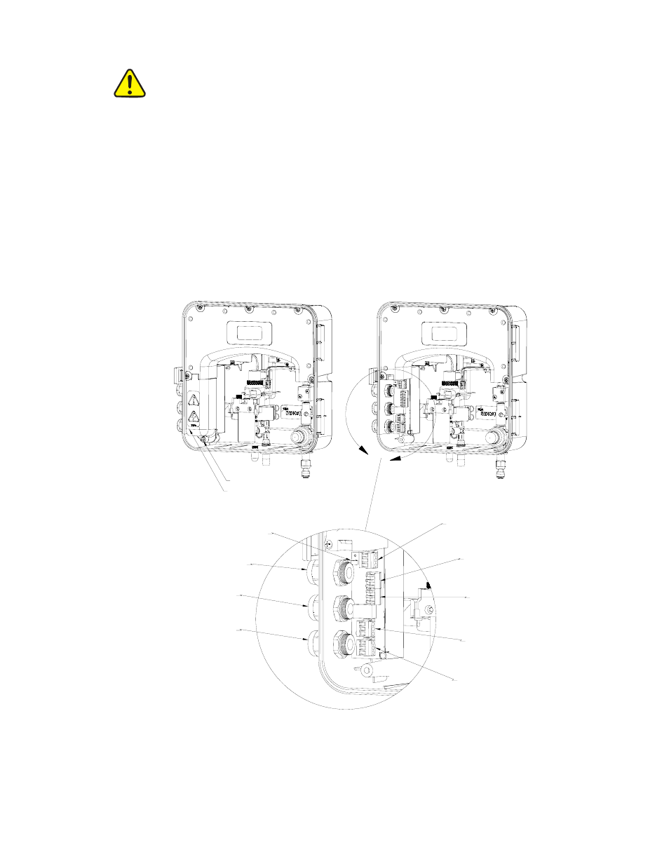
4.3 Electrical Connections
All of the electrical connections to the instrument are made at the termination area which
is located on the left side of the instrument. Remove the high voltage cover by loosening
the captive screw. Refer to figure 5. The connections are labeled and are self-descriptive
(see Figure 5). Please follow all local and government recommendations for installation
of electrical connections to and between the instrument and other peripheral devices.
High Voltage Cover
Captive Screw
Power
Terminal
Block
Alarm #2
Terminal
Block
Alarm #1
Terminal
Block
RS-485
Terminal
Block
4-20mA
Terminal
Block
Power Cable
Strain Relief
Anchor
Power
Bulkhead
Alarms
Bulkhead
Communication
Bulkhead
Figure 5: Electrical Connections for the Instrument
CL500 (2/08)
Page 8
REV 2.0