A-100ne, Circuit board connections, Page 7 – Xylem A-100NE CHEMICAL PUMPS User Manual
Page 7
A-100NE
Page 7
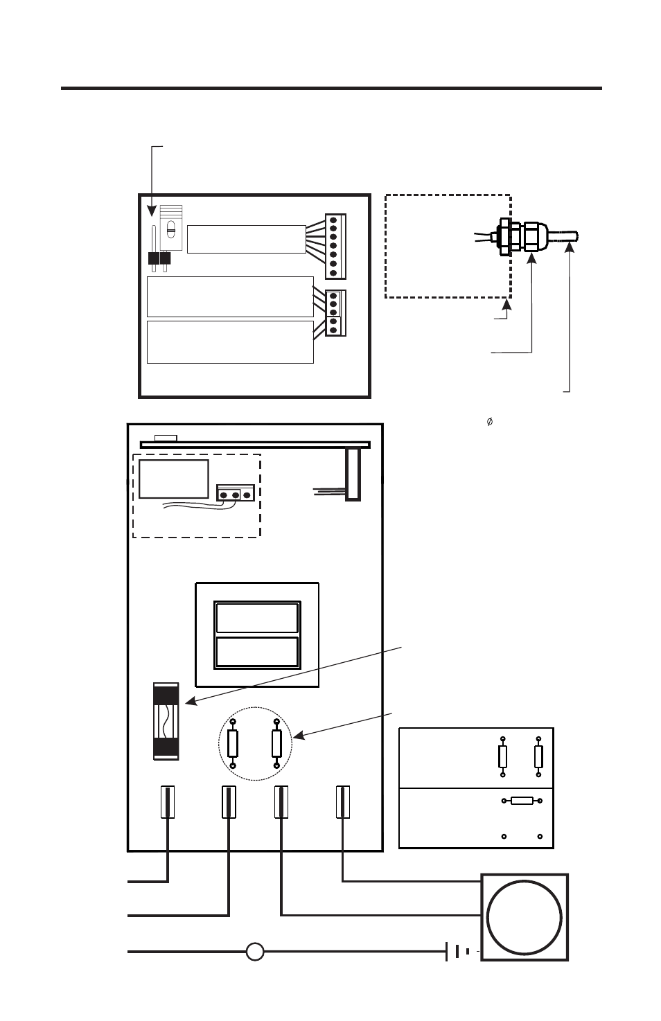
ACCEPTABLE CABLE JACKET RANGE:
.118 - .255 INCH .( 3,0 - 6,5 MM)
EXTERNAL INPUT CABLE
CIRCUIT BOARD CONNECTIONS
AC
MOTOR
Neutral (blue/brown/red)
Hot (yellow)
Ground (green)
Ground (green)
Common
Hot
AC
Input
Power
Power Circuit Board
(Top view)
Protector Fuse
2 Amps, 250 Volt AC
(little Fuse #235002
or Equivalent)
R R
2A
250VAC
T3
T2
T1
T4
LINE
HOT
LINE
NEUTRAL
MOTOR
NEUTRAL
MOTOR
SWITCHED
115V 50/60Hz
INPUT VOLTAGE
RESISTOR PLACEMENT
220V 50/60Hz
230V 50/60Hz
R R
R
MA = BLUE
GND = BLACK
RELAY = PURPLE (2)
VDC = ORANGE
VS = RED (+17V DC)
PLS = WHITE
JUNCTION BOX
LIQUID-TIGHT
CONNECTOR
MTR = BROWN
Alarm Relay
3A/125VAC
N/C
CO
M
N/
O
Purple connection wires
Default is N/O
VS
VDC
MA
MTR
GND
PLS
CN3
VS
FVS
GND
TFD
GND
FVS+
CN4
Control Circuit Board
(Back view)
Program Disable Jumper - Located on front of Control board.
Un-installed = enable front panel programming (default)
Installed = disable front panel programming
External input connections
6 Wire bundle to junction box
Flow verification sensor connector
3 Wire bundle to junction box.
red/black/yellow
Tube failure detection sensor connector
2 Wire bundle to pump head sensor
(A-100N series pumps only)