A-100ne, Fvs) flow verification system, Inlet adapter outlet adapter – Xylem A-100NE CHEMICAL PUMPS User Manual
Page 11: Fvs sensor
A-100NE
Page 11
Confirm the FVS flow range - The Flow
Verification Sensor (FVS) will only function
within its operating range. Sensor model FV-
100-6V has an operating range of 30-300
ml/min (1-10 oz/min). If the pump’s output is
less than 30 ml/min (0.5 ml/sec), the sensor
will not detect chemical and a signal will not
be sent to the pump.
OPERATING
FLOW RANGE
(ml/min)
30-300
FV-100-6V
100-1000
FV-200-6V
200-2000
FV-300-6V
300-3000
FV-400-6V
500-5000
FV-500-6V
700-7000
FV-600-6V
SENSOR
MODEL
NUMBER
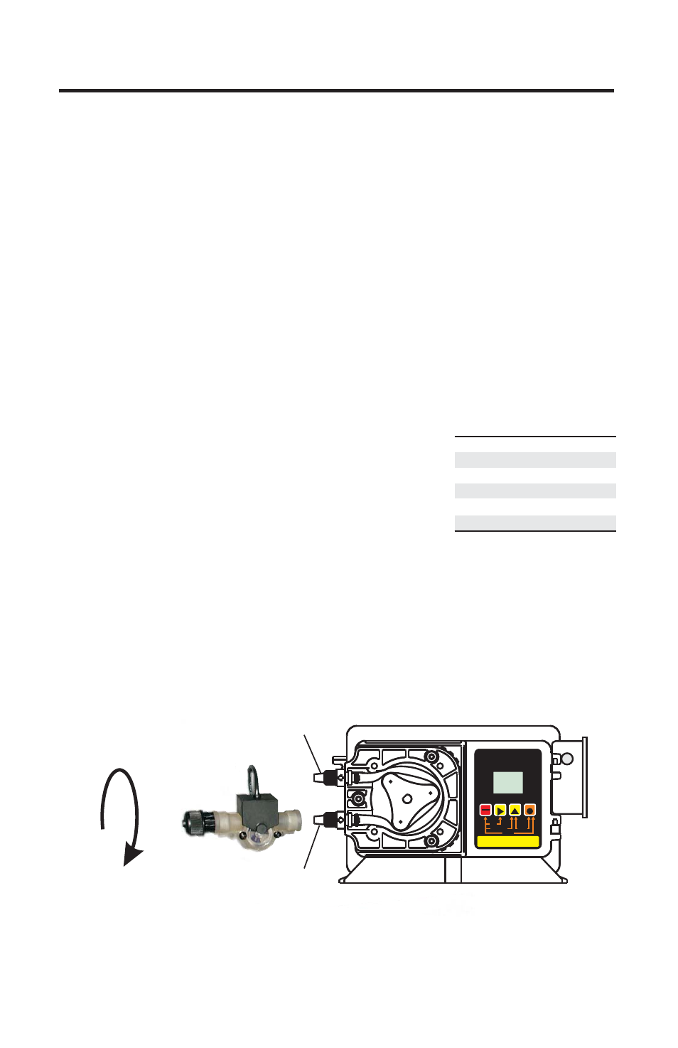
Install the FVS Flow Sensor - The Flow Verification Sensor (FVS) should
be installed on the inlet (suction) side of the pump tube. The sensor includes
a PVC tubing insert, located inside the sensor’s female thread connection,
that is designed to seal the sensor onto the pump tube inlet adapter. Thread
the sensor onto the pump tube until the tubing insert is snug against the
pump tube inlet fitting - do not over-tighten.
Connect the red/white, black, and white wires from the sensor to the red,
black, and yellow wires located in the pump’s junction box. See page 7.
Contact Closure Alarm Output - A contact closure output (relay) is
provided with the FVS system. The relay can be configured for normally
open (factory default) or normally closed operation by properly positioning
the connector plug on the circuit board (see page 7).
!
(FVS) Flow Verification System
The A-100NE is equipped with a
Flow Verification System which is designed to stop the pump and provide a
contact closure output in the event the sensor does not detect chemical
during pump operation. This could indicate a clogged injection fitting,
empty chemical solution tank, worn pump tube, loose tubing connection,
etc.
To allow the pump to clear any gasses that may have accumulated during
stopper operation (such as with chlorine), an alarm delay time value from 1-
256 seconds must be programmed (An alarm delay value of 000 seconds
disables the FVS system). The pump will stop, and the alarm mode
activated, if no pulses are received by the pump and the alarm delay time
period has ended. Press the STAND-BY button twice to clear the alarm and
restart the pump. The Flow Verification Sensor is sold as an optional
accessory.
-
Inlet Adapter
Outlet Adapter
RUN
STANDBY
RUN
FIELD
DIGIT
MODE
PROGRAM
STAND-BY
PRIME
MINIMUM
MAXIMUM
INPUT MODES
1 - MANUAL
2 - 4-20mA
3 - 0-10VDC
4 - 0-1000 Hz
PROGRAM
RESET SERVICE
PRIME
DISPLAY
DIGITAL TIMER PUMP
1
VDC
SERVICE
1000
ALARM
mA
Hz
MODE
TFDFVS
ON-TTOT-TSECMINHRDAY
5 - PULSE (BATCH)
FVS Sensor