A-100ne, 2 input power connections, Suction tube chemical container with cover – Xylem A-100NE CHEMICAL PUMPS User Manual
Page 5: Parts locator drawing
A-100NE
Page 5
CAUTION: Proper eye and skin protection must be
worn when installing and servicing the pump.
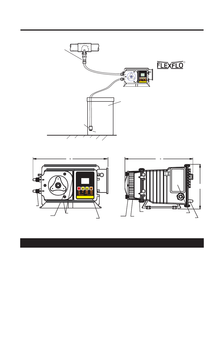
TYPICAL INSTALLATION
R
Suction
Tube
Chemical
Container
with cover
RUN
STANDBY
RUN
FIELD
DIGIT
MODE
PROGRAM
STAND-BY
PRIME
MINIMUM
MAXIMUM
INPUT MODES
1 - MANUAL
2 - 4-20mA
3 - 0-10VDC
4 - PULSE (Hz)
PROGRAM
RESET SERVICE
PRIME
DISPLAY
VARIABLE SPEED PUMP
% SPEED
1
MODE
VDC
SERVICE
1000
ALARM
mA
Hz
Discharge
Tube
Strainer
Ceramic Weight
Injection / Check valve
with 1/4” and 1/2” male
pipe threads.
Mount in upward position
to prevent trapped gasses
in the injection fitting.
Wall or shelf mount
away from the top of the
solution tank. Chemical
fumes can damage the
unit.
5.2 Input Power Connections
! Be certain to connect the pump to the proper supply voltage. Using the
incorrect voltage will damage the pump and may result in injury. The
voltage requirement is printed on the pump serial label.
! Removable resistors on the circuit board are factory preset for the correct
voltage. See page 7 Circuit Board Connections diagram for details.
! The pump is supplied with a ground wire conductor and a grounding type
attachment plug (power cord). To reduce the risk of electric shock, be
certain that the power cord is connected only to a properly grounded,
grounding type receptacle.
Note: When in doubt regarding your electrical installation, contact a
licensed electrician.
WARNING: Risk of electric shock.
9
2
1
Control
Control Cover
Pumphead
Junction Box
Rear Plate
Pumphead
Cover
6.0
Pumptube
Assembly
Rotor
Assembly
9
8
1
Slide Clamps**
RUN
STANDBY
RUN
FIELD
DIGIT
MODE
PROGRAM
STAND-BY
PRIME
MINIMUM
MAXIMUM
INPUT MODES
1 - MANUAL
2 - 4-20mA
3 - 0-10VDC
4 - PULSE (Hz)
PROGRAM
RESET SERVICE
PRIME
DISPLAY
DIGITAL TIMER PUMP
PARTS LOCATOR DRAWING