Xylem H-3553 User Manual
Page 9
Using a SDI-12 master device, like the XL series DCP, send the “0M!” measurement command to the H-3553.
Wait about 6 seconds, and then send the “0D0!” data command and verify the data retrieved with the example
below.
Data format: “a + A.AA + B.BBB + CC.C + DD.D + E.EE + FF.F”
a = SDI-12 sensor address
A.AA = Stage (Feet)
B.BBB = Pressure (PSI)
CC.C = Temperature (°C)
DD.D = Sensor Interface Battery (Volts)
E.EE = Tank Pressure (PSI)
F.FF = Compressor Battery (Volts)
Example: “0 + 1.35 + 0.585 + 19.8 + 13.6 +
3.55 + 12.3”
Getting Started
7
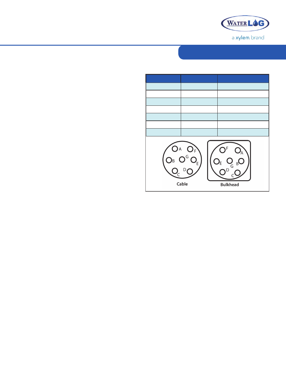
Colors
signal
Cable/Bulkhead
Red
+12 VDC
F
Black
GND
E
Yellow
SDI-12 Data
G
Blue
4-20mA +
C
Green
4-20mA -
D
Orange
RS-485+
A
Brown
RS-485-
B
Table 2-1: Main I/O Sensor Interface Cable
The H-3553s display has a ‘Read’ button that
when pressed will cause the unit to initiate a new
measurement and update the display. Measurement
requests from an attached SDI-12 data logger will
also cause the display to update.
If the ‘Read’ button is pressed and held until
the display starts flashing, the Adjust screw may
be turned to increase or decrease the current
stage value. Turning the Adjust screw slowly
will change the hundredths (or thousandths
based on the digit setting) digit while turning
the screw fast changes the ones digit. This
allows one control to make both fine and course
adjustments.
If the ‘Read’ button is held down while the
H-3553 is being powered up, the display will
show the current SDI-12 address. The SDI-12
Using the Display
address may be changed using the Adjust screw. Turning the Adjust screw will change the address
in the range of 0 to 9. When the Read button is released the new SDI-12 address is saved and the
display switches to the normal stage readout. To change the SDI-12 address again, the power must
be disconnected and the special power-up sequence repeated.
When the ‘Purge’ button is pressed a new measurement will be initiated; following the
measurement, a line purge will begin. For more information see the Purge section in Chapter 4.
When the ‘Tank Release’ button is pressed the valve holding the air in the tank will be opened,
allowing the air stored in the tank to be released. This button can be useful when troubleshooting
the unit.
Make Measurement