Xylem IMVIC R01 Model VIC Vertical Industrial Turbine Can Pumps User Manual
Page 18
18
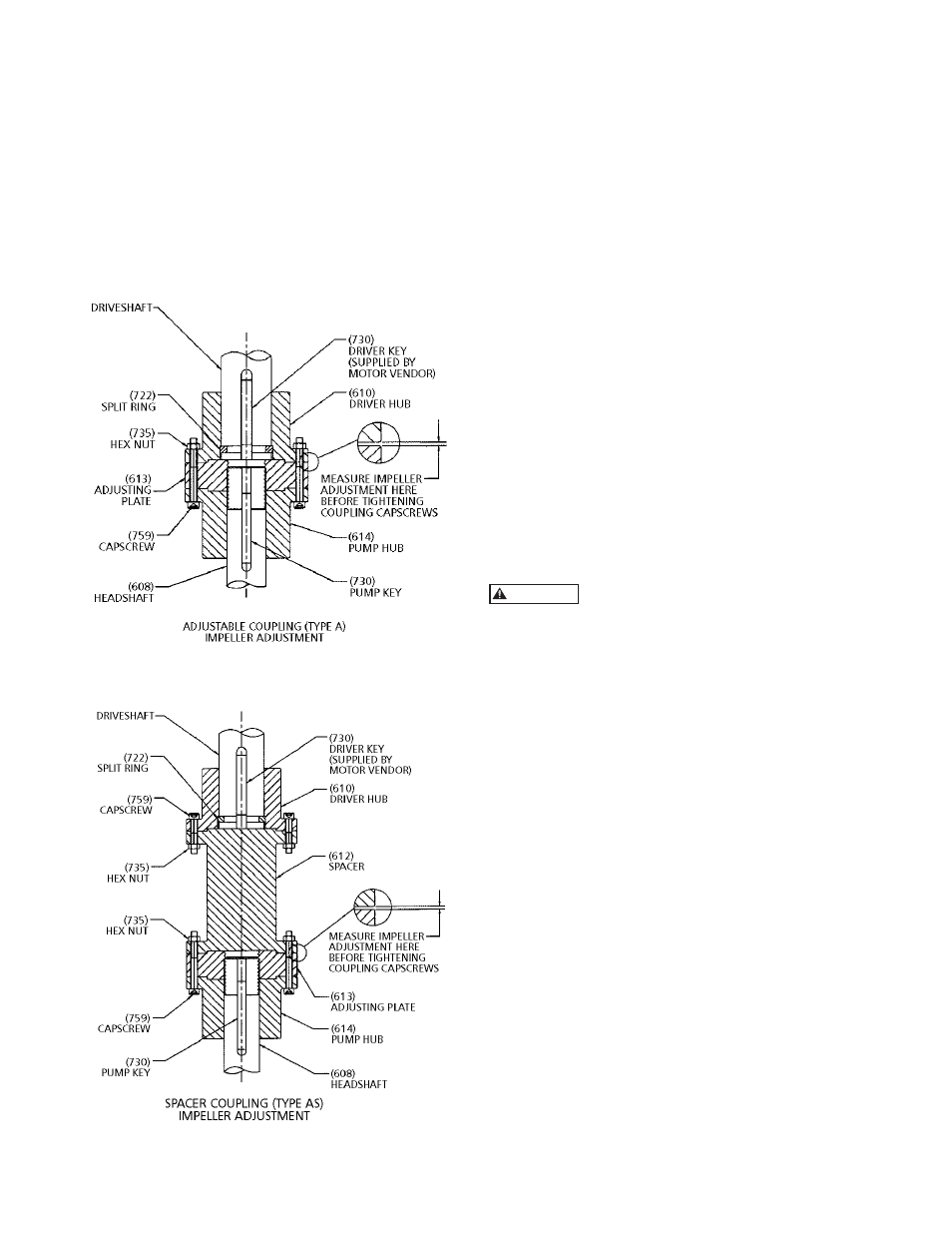
2. After impeller adjustment, align adjusting plate (613)
with the pump hub (614), and tightly draw coupling
flanges together with capscrews (759) and nuts
(735). (See figure 9 and 10).
3. Check shaft run out with dial indicator. For
mechanical seal installation, the run out should be
0.005 or less.
4. Set seal after impeller adjustment. Securely tighten
all set screws in the collar. Remove the spacer
between the gland plate and collar. Retain spacer for
future resetting of seal.
NOTE: When impellers are reset, the seal must also be
reset.
Figure 11
Figure 12
ENCLOSED IMPELLERS
For enclosed impellers obtain the clearance between the
adjusting plate and driver hub or spacer as specified on
the outline drawing. See Figure 11 or 12.
INSTALLING THE GREASE LUBRICATED THRUST POT
This type of thrust pot and the motor stand are
assembled on the discharge head by the factory. This
thrust pot is designed to be used with NEMA Vertical
C-face motors. The motor shaft and the pump shaft have
to be coupled with flexible coupling.
INSTALLATION:
1. Install both coupling halves prior to mounting
the motor. Refer to the coupling manufacturer’s
instructions.
2. Using the lifting lugs on the motor, carefully lower
the motor onto the motor stand of the thrust pot
(See Figure 13) and align the bolt holes.
3. Install the bolts finger tight.
4. Make temporary electrical connections according
to tagged leads or diagram attached to the motor.
Motor must rotate counterclockwise when viewed
from the top. See arrow on pump name plate. If
motor does not rotate counterclockwise, you can
change the rotation by interchanging any two leads.
Before beginning any alignment procedure,
make sure driver power is locked out.
Failure to lock out driver power will result in serious
physical injury.
ALIGNMENT OF FLEXIBLE COUPLING:
Alignment of the pump and motor is extreme importance
for trouble-free mechanical operation. Straight edge
alignment by an experienced installer proves adequate for
most installations.
1. Check for coupling alignment by laying a straight
edge across both coupling rims at four points 90º
apart.
2. Move motor until straight edge rests evenly at each
position. Repeat procedure until correct alignment is
achieved.
3. Install flexible sleeve between the hubs per the
manufacture’s instructions.
4. Tighten all motor bolts.
NOTE: Be sure the relief fitting (#11 in Figure 13) is
clear of paint or any other obstructive material.
Otherwise it will cause premature failure of the
thrust pot and is not covered under warranty.
WARNING