Xylem IMVIC R01 Model VIC Vertical Industrial Turbine Can Pumps User Manual
Page 11
11
1. Prior to installing the bowl assembly, check that
all capscrews are tight. Turn the pump shaft by
hand and make sure it turns freely. Remove all
accumulated dust, oil, or other foreign material
from the external surfaces.
2. If a suction strainer is provided, assemble it to the
suction bell (or suction bowl).
Figure 5
3. Place two I-beam supports across the base plate
opening, strong enough to safely support the weight
of the entire pump assembly. These I-beams should
be connected by threaded rods and nuts so as to
clamp them firmly together for the portion to be
supported. (See Figure 5).
4. Place a suitable hoist or derrick over base plate
opening with the hook in the center. Place the
elevator clamps just below the discharge bowl. Place
the elevator clamps just below the discharge bowl.
For flanged column install two threaded eyebolts
through the discharge bowl bolt holes 180º apart
for flanged column. For threaded discharge utilize
a lifting bail sized to handle the weight of the bowl
assembly and suction apparatus. Attach a sling to the
elevator clamps, eyebolts, or lifting bail and hoist it
into position.
5. Carefully lower bowl assembly, guiding the unit so it
does not strike the sides of the opening. Continue
to lower bowl assembly until the elevator clamps
or discharge bowl flange rests firmly on the I-beam
supports.
6. Place a cover over the discharge bowl opening to
prevent entrance of dirt or other foreign matter
until ready for installation of the column assembly.
Do not drop any foreign object into the
bowl assembly. Such an object can cause
serious damage to the pump and any downstream
components. Any foreign object dropped into the bowl
assembly must be retrieved prior to continuing assembly.
THREADED COUPLING INSTALLATION
NOTE: Shaft threads are left-handed.
When the threaded coupling is not installed on the
pumpshaft, install as follows:
1. Coat a thin film of oil to the threads on the lineshaft
(646) and the coupling (649) (for non-galling
material, or Molykote if galling material).
2. Install threaded coupling onto pumpshaft by
threading it on for one-half its length. A fine
wire inserted in the drill hole at the center of the
coupling can be used as a gauge to determine
when the coupling is correctly positioned on the
pumpshaft. Remove the wire after installed the
coupling.
Use “MOLYKOTE” Dow Corning or
equal for all galling material such as 316
stainless steel.
INSTALLING THE COLUMN
OPEN LINESHAFT
Pump lineshafts are coupled with either threaded
or keyed couplings. Follow only those procedures
appropriate for the type of lineshaft coupling supplied.
When provided, see the Certified Pump Outline Drawing
for the number of column and shaft sections required.
1. Check the headshaft (608) and lineshaft (646) for
straightness. Average total runout should be less
than 0.0005” T.I.R. per foot, not to exceed 0.005”
T.I.R. for every 10 feet of shafting.
2. Hoist the first piece of lineshaft over the bowl
assembly. Lower the lineshaft until the bottom end
is properly aligned with the coupling of the pump
shaft. Apply a thin film of oil to the threads on the
lineshaft (646) and the coupling (649) (for non-
galling material, or Molykote if galling material).
Use “MOLYKOTE” Dow Corning or
equal for all galling material such as
316 stainless steel.
3a. With lineshaft in the proper position on the
coupling, screw lineshaft into the coupling manually
until resistance is felt. A fine wire inserted in the
hole at the center of the coupling can be used as a
gage to determine when the coupling is correctly
positioned on the shaft. Remove the wire after
installing the shaft. Completely tighten the joint
by using a pair of pipe wrenches. Use care not to
damage any bearing journal areas on the shaft.
NOTE: Shaft threads are left-handed.
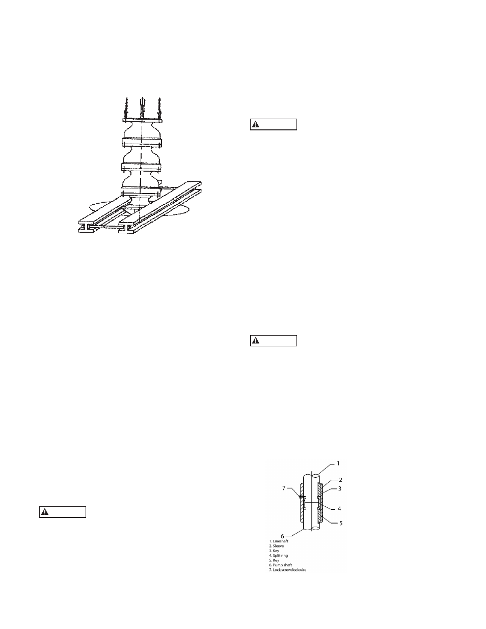
3b.
With a keyed coupling
insert the key into the
pump shaft. Lower the
sleeve over the pump shaft,
to approximately 1.0 in
(25.4 mm) below the top
of the shaft. Then lower
the lineshaft until it touches
the pump shaft. Insert the
split ring into the grooves
of the pump shaft and
lineshaft. Raise the sleeve
until it covers the split ring,
then insert the key into the
lineshaft. Raise the sleeve to the top of the key and
secure the sleeve to the split ring with a lock screw
and lock wire.
CAUTION
CAUTION
CAUTION