Xylem IMVIC R01 Model VIC Vertical Industrial Turbine Can Pumps User Manual
Page 16
16
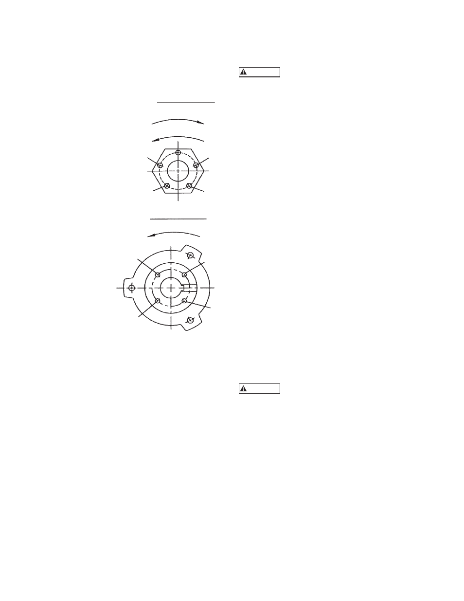
IMPELLER ADJUSTMENT FOR ALL HOLLOW
SHAFT DRIVES
NOTE: Shaft adjustment up or down is accomplished by
turning the adjusting nut (604) Figure 8.
NOTE: There are five holes in the adjusting nut and
only four in the motor coupling. See Figure 8.
1. With shafting all the
way down and the
impellers resting on
their seats, turn the
adjusting nut (604)
in counter-clockwise
direction, thus lifting
the shaft, until the
impellers just clear their
seats and the shaft/
motor turns free by
hand. This removes
all deflection from the
shaft.
2. For enclosed impellers,
make another two turns
on the adjusting nut.
(3 turns for 12 thread/
inch shaft) Line-up
one of the holes in
the adjusting nut
with the nearest
hole in the driver
coupling. Insert
the capscrew
in the hole and
tighten it.
Figure 8
NOTE: 1.00” and 1.18” diameter shafts are 12 thread
per inch (tpi), 1.50" through 2.44" are 10 tpi, all
larger sizes are 8 tpi.
3. For Open Impellers, Align hole “A” in the adjusting
nut (604) and hole “C” in the driver coupling
(See Figure 8) or whatever similar holes are in like
position. If care is exercised, this will give an initial
impeller clearance of 0.001” to 0.003” depending
on shaft size or the pitch of the thread.
4. Insert capscrew into hole “B” provided these are
the nearest matching holes for counter-clockwise
rotation of adjusting nut, turn adjusting nut counter-
clockwise until holes “B” and “D” line up. This
gives 1/20 of a turn which is 0.004” on 12 tpi shaft
or 0.005” on 10 tpi shaft.
5. Normal impeller clearance for the open impeller is
considered to be 0.015” for the first 10 feet of the
column length and 0.010” additional clearance for
each 10 ft of length thereafter. This can be reduced
in some instances where is necessary, but should
not be attempted without consulting the factory or
factory serviceman is present.
INSTALLATION OF A SOLID SHAFT DRIVER
NOTE: When pump is supplied with a thrust pot, do
not secure driver to discharge head until after
the thrust pot and flexible coupling are installed.
Do not work under a heavy suspended
object unless there is a positive support
and safe guard which will protect personnel should a
hoist or sling fail.
The coupling between the driveshaft and the head shaft
may be a non-spacer type (see Figure 9), or a spacer type
(see Figure 10). The latter is used on pumps furnished
with a mechanical seal to permit servicing of the seal
without removal of the driver.
1. Attach a sling to the lifting lugs of driver, hoist
motor, inspect the mounting surface, register, and
shaft extension, and clean these surfaces thoroughly.
If any burrs are found, remove burrs with a smooth
mill file, cleaning thoroughly afterward.
2. Orient the motor conduit box in the required
position. Align the motor mounting holes with the
mating tapped holes on the discharge head. Lower
the motor until the registers engage and the motor
rests on the discharge head. Secure motor with
capscrews provided.
3. On drivers having a nonreverse ratchet or pins,
manually turn the driver shaft clockwise viewed
from the top until the nonreverse ratchet or pins
fully engage.
4. Lubricate motor bearings in accordance with
instructions given on lubrication plate attached to
the motor case.
NOTE: Please read and follow the motor manufacturer’s
instructions before lubricating the motor
bearings. Too much lubricant can cause the
bearings to overheat prematurely.
The motor must not be tested for direction
of rotation when coupled to the pump.
If pump should rotate in the wrong direction, serious
damage to the pump and motor would result. Also
serious injury to personnel could result.
5. Make temporary electrical connections according
to tagged leads or diagram attached to the motor.
Motor must rotate counterclockwise when viewed
from the top. See arrow on pump name plate. If
motor does not rotate counterclockwise, you can
change the rotation by interchanging any two leads.
6. Motor shaft end play adjustment: if required,
motor shaft end play shall be checked with a dial
indicator prior to connecting the pump coupling to
the solid shaft motor. Consult the applicable motor
manufacturers instruction manual for detailed
information on motor shaft end play.
(604) ADJUSTING NUT
LOWER IMPELLER
RAISE IMPELLER
MOTOR COUPLING
ROTATION
A
B
G
D
H
C
E
F
WARNING
WARNING