Xylem IMVIC R01 Model VIC Vertical Industrial Turbine Can Pumps User Manual
Page 14
14
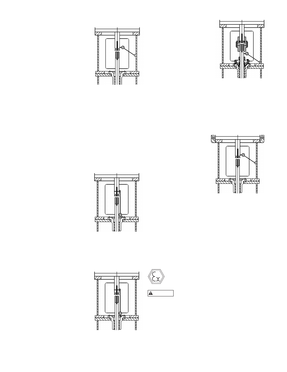
MECHANICAL SEAL ALIGNMENT
CONCENTRICITY OF MOTOR SHAFT
1. Install the dial indicator as
shown, with the base attached
to the motor support.
2. Rotate the motor shaft by
hand while you read the dial.
3. Make sure that the runout
does not exceed NEMA
standards, 0.002 in (0.05
mm) maximum TIR.
4. If the indicator reads higher
than 0.002 in
(0.05 mm)TIR, loosen the four motor hold-down
bolts and relocate the motor on the motor base
register.
5. Obtain the desired position.
6. Tighten the hold-down bolts and repeat the
indicator reading.
Note: Adding or removing shims between the motor
and the discharge head helps alignment in the
vertical direction. The motor may also have to be
adjusted in the horizontal direction for alignment.
FLATNESS OF THE SEAL HOUSING
For this measurement, remove the mechanical seal if the
dial indicator stylus cannot rotate 360° on the top surface
of the seal gland.
1. Install the dial indicator as
shown, with the base 1)
Remove the lower coupling
components and attach the
base of the dial indicator to
the motor shaft.
2. Place the stylus at the top
surface of the seal gland, or
at the top surface of the seal
housing.
3. Slowly rotate the motor
shaft 360°.
4. Check that the face of the seal housing is square with
the shaft to within 0.002 in (0.05 mm) TIR.
CONCENTRICITY OF THE SEAL HOUSING
This measurement requires that you remove the
mechanical seal.
1. Install the dial indicator as
shown.
2. Rotate the motor shaft
by hand and run the
indicator in the inside-
machined surface of the
seal housing in order to
determine the concentricity.
3. If the indicator reads
higher than 0.004 in (0.10
mm) TIR, loosen the four
motor hold-down bolts and
relocate the motor on the motor base register.
4. Obtain the desired position.
5. Tighten the hold-down bolts and repeat the
indicator reading.
CONCENTRICITY OF THE HEADSHAFT
1. Reinstall the mechanical
seal if it was removed for
the flatness or concentricity
measurement.
2. Install the coupling assembly
and adjust the impeller.
3. Attach the base of the dial
indicator on the discharge
head or motor support.
4. Place the stylus on the shaft
between the top of the seal
and the bottom of the pump coupling.
5. Slowly rotate the motor shaft 360°.
6. Check that the shaft runout is within 0.004 in
(0.10 mm) TIR, or as required by specification.
7. Drill and dowel the pin in three places in order to
secure the motor to the motor base after you obtain
the required runouts.
CONCENTRICITY OF MOTOR SHAFT USING
JACKSCREWS
1. Install the dial indicator
as shown, with the base
attached to the motor
support.
2. Rotate the motor shaft by
hand while you read the
dial.
3. Make sure that the runout
does not exceed NEMA
standards, 0.002 in (0.05
mm) maximum TIR.
4. If the indicator reads higher than 0.002 in
(0.05 mm) TIR, using the jackscrews relocate the
motor on the motor base (sometimes no register).
5. Obtain the desired position.
6. Tighten the hold-down bolts (not the jackscrews)
and repeat the indicator reading.
Note: Adding or removing shims between the
motor and the discharge head helps alignment in
the vertical direction. The jackscrews are provided
to adjust the motor in the horizontal direction for
alignment.
INSTALLING THE DRIVER
When installed in a potentially explosive
environment, please ensure the motor is
properly certified.
Serious damage may result if pump is run
in the wrong direction.
NOTE: When pump is supplied with a thrust pot, do not
secure the driver to discharge head until after the
thrust pot and flexible coupling are installed.
INSTALLATION OF A HOLLOW SHAFT DRIVER
This refers to either VHS type electric motors or hollow
shaft type gear drives. A small paragraph will be devoted
to combination electric motor and right angle gear
drives.
WARNING