Xylem IMVIC R01 Model VIC Vertical Industrial Turbine Can Pumps User Manual
Page 15
15
Do not work under a heavy suspended
object unless there is a positive support
and safe guards which will protect personnel should a
hoist or sling fail.
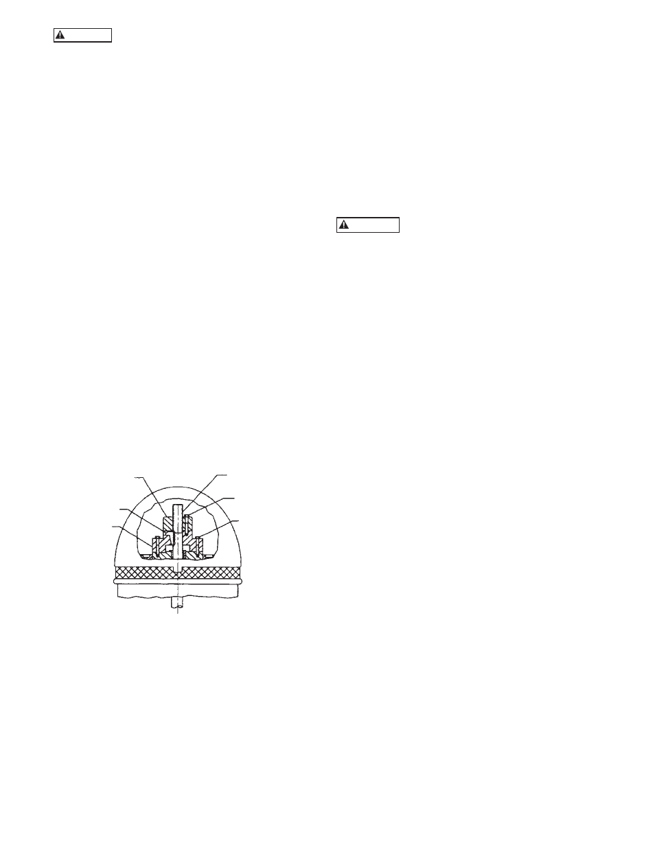
1. The driving mechanism of all hollow shaft driver is
shown on Figure 7. The head shaft (608) extends up
through the quill or hollow shaft of the driver and
is held in place by an adjusting nut (604), which not
only carries all the static and hydraulic thrust of the
impellers and shaft, but also provides the adjustment
for the impeller clearances. The head shaft is
connected to top shaft (or stub shaft) by a threaded
coupling or a rigid flange coupling.
2. Attach a sling to the lifting lugs of driver and hoist
the driver up. Inspect the mounting surface, register
and clean these surfaces thoroughly. If any burrs
are found, remove burrs with a smooth mill file,
cleaning thoroughly afterward.
3. For motor, orient the motor conduit box in the
required position. For the right angle gear, orient
the input shaft to the desired position. Align the
driver mounting holes with the mating tapped holes
on the discharge head. Lower the driver until the
registers engage and the driver rests on the discharge
head. Secure driver with capscrews provided.
4. Lubricate the driver bearings in accordance with
instructions given on lubrication plate attached to
the driver case. (Or refer to IOM of the driver)
5. After lowering and orienting the driver as explained
above, remove the drive coupling and the hold
down bolts (See Figure 16). Be sure to mark the
location of the coupling before removing it.
Figure 7
6. Lower the head shaft through the motor quill shaft
to meet the shaft coupling. Apply a thin film of oil
to head shaft threads (if non-galling material) and
screw into the shaft coupling (located above the
stuffing box). Make sure the shaft is not damaged in
any way. Tighten the joint.
7. Check that the head shaft centers inside the driver
quill shaft within 0.06” (1.5mm). If it does not,
misalignment is indicated.
8. Any head shaft misalignment with driver quill
shaft could be caused by a bent head shaft, burrs,
or foreign matter between shaft ends or any of the
mounting flanges: motor flange to discharge head
top flange, discharge head base flange to base plate
or the base plate itself could be out of level. If the
latter, shimming between it and discharge head base,
will correct it. Also, check concentricity of motor to
motor-stand (if provided) to discharge head.
9. With the motor in place and the head shaft
projecting through the motor quill shaft, make
temporary electrical connection to check the motor
rotation. (Be sure to remove the ratchet pins or balls
before checking motor rotation.) Motor must rotate
counter-clockwise when viewed from the top. See
arrow on pump name plate. If motor does not rotate
counter-clockwise, you can change the rotation by
interchanging any two leads.
Never check motor rotation with the drive
coupling in place. The bore clearance
between the drive coupling and the pump shaft O. D.
is so close that should the motor spin with this shaft
stationary, galling and locking together is very likely to
take place.
10. Install motor drive coupling. (Be sure to line up the
match mark made at step 5.) Insert the ratchet pins
if a non-reverse ratchet is used. Match the coupling
lugs with corresponding holes in motor. Tighten
hold down bolts evenly, making sure driver coupling
is properly seated in the register fit.
11. Fit gib key (730) into keyway, by filing if necessary,
to where there is a snug but sliding fit. This key
must be able to be removed by gentle leverage with
a screwdriver under it.
12. Be careful that the gib key (730) is not too high so
as to hold up the adjusting nut (604) from seating
on the drive coupling. If it is, cut off some length of
the key.
13. Install adjusting nut (604) to hand tight.
COMBINATION ENGINE AND MOTOR DRIVES
1. On combination drivers, the motor is invariably on
top with a projecting head shaft extension.
2. Follow all procedures outlined in the previous
paragraph, except that the motor must be lowered
over this extended head shaft and great care must be
taken to center it exactly so as not to bump or mis-
align the shaft while the motor is being lowered into
place.
3. There are several methods of running engines
without electric motors and vice versa, requiring
simple adjustment to the combination drive, but
they are too numerous to mention here and can be
obtained from the gear manufacturers instructions
included with the shipment.
HEAD SHAFT (608)
CAPSCREW (760)
ADJUSTING NUT
HOLD
DOWN BOLT
(604) ADJUSTING
NUT
(730) GIB KEY
DRIVE
COUPLING
CAUTION
WARNING