Bell & Gossett P80925B Zone Trol Zone Pump Controller ZT-6 User Manual
Page 3
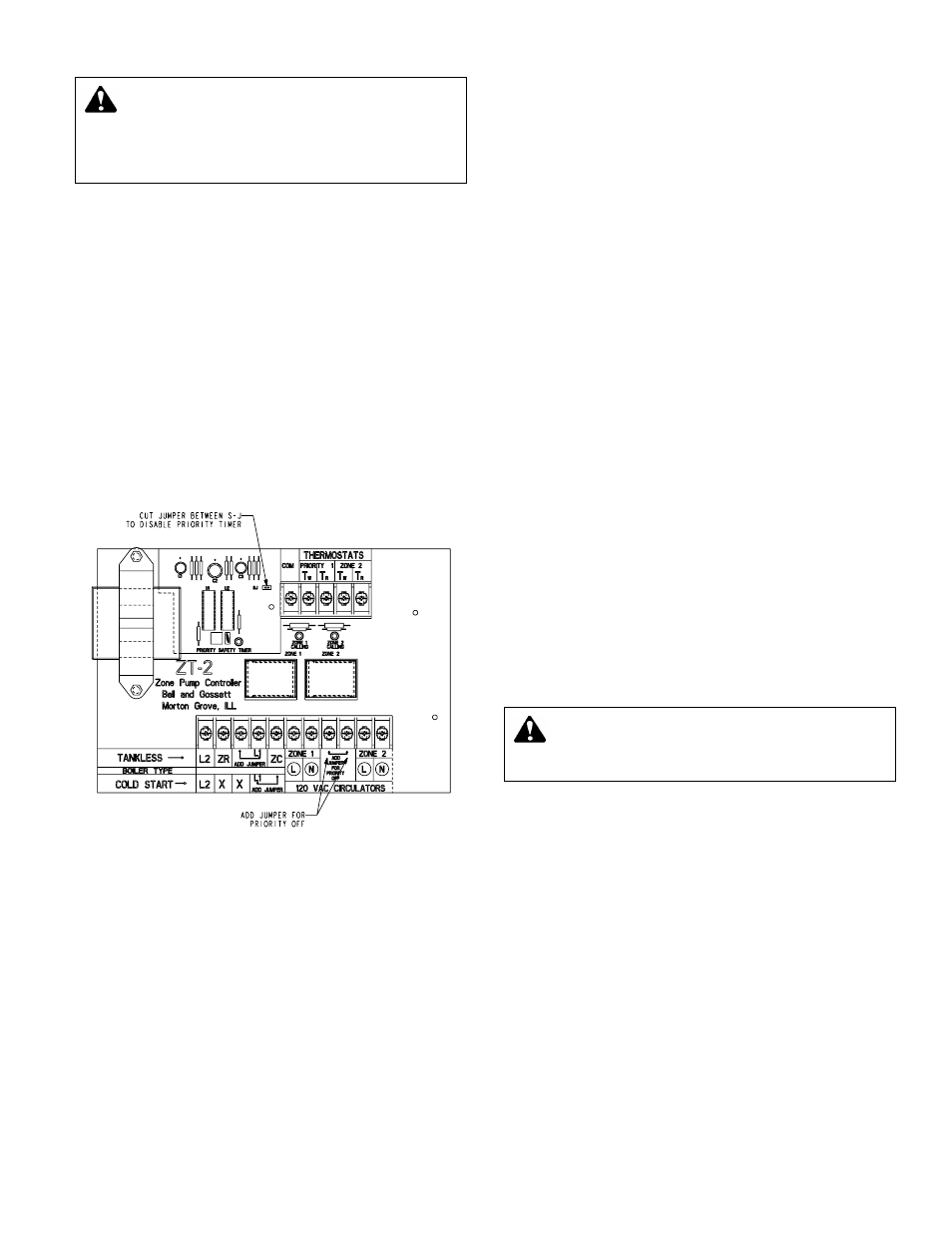
“Tankless Coil” Boiler Applications
The “tankless coil” boiler application activates the boiler and
permits circulator operation only after boiler water has reached
the low temperature limit settings. If boiler temperatures drop
below the low limit setting, all circulators will cease operation
until the low limit temperature of the boiler is satisfied.
1) A factory installed jumper is connected between the L1/ZC
terminals. Move the jumper to the terminal as shown on
the circuit board.
2) Attach the low voltage SPST thermostat leads to the
respective thermostat teminals.
3) Attach circulator leads to respective terminals.
4) Connect supply voltage line to the L1 and L2 terminals
located in the lower center portion of the circuit board.
5) Connect the ZC/ZR terminals to the corresponding ZC/ZR
terminals on the boiler aquastat. The XX terminals are not
used. Note: The required aquastat connections may vary,
depending on model. Refer to aquastat manufacturers'
instructions to ensure appropriate interconnections.
Priority
The ZT-2 and ZT-3 pump controllers are supplied from factory
ready for priority applications. When the priority zone 1 circu-
lator is actuated, the other circulator(s) will not operate. The
ZoneTrol has a 30 minute timer on the priority zone. After
30 minutes of continous operation, the priority zone function
will default allowing all zones to operate preventing possible
house freeze up. The timer is automatically reset after the
priority zone is satisfied.
For applications where priority is not desired, add second
jumper (remove one from L1 and ZC terminals) between the
terminals that are marked “ADD JUMPER FOR PRIORITY
OFF” and cut jumper wire between S-J (see drawing). This will
disable the priority feature allowing all zones to operate inde-
pendent of each other.
SERVICE INSTRUCTIONS
The ZoneTrol is quality constructed and should provide many
years of trouble-free service when installed and operated in
accordance with the instruction manual. To ensure optimum
long-term performance, once each heating season, visually
inspect the unit to check the condition of the contacts on the
plug-in replaceable relays. Replace the relay(s) if contacts
appear pitted or severely blackened.
The 24 volt fuse is temperature sensitive and will automatically
reset after a couple of minutes cooling time.
WARNING: Potential electrical shock. Disconnect all
power to unit before removing chassis cover. Failure
to follow these instructions could result is serious personal
injury or death and property damage.
3
“Cold Start” Boiler Applications
The “cold start” boiler application provides circulator operation
whenever a zone thermostat calls for heat (regardless of boiler
water temperature) and will start the burner when used in con-
junction with an isolated end switch connected to the aquastat
on the boiler.
1) A factory installed jumper is connected between the L1/ZC
terminals. Leave the jumper in this position.
2) Attach the low voltage SPST thermostat leads to the
respective thermostat teminals.
3) Attach circulator leads to respective terminals.
4) Connect supply voltage line to the terminals L1 and L2,
located in the lower center portion of the circuit board.
5) Connect isolated switch (terminals XX) to TT terminals on
boiler aquastat. Note: The required aquastat connections
may vary, depending on model. Refer to aquastat manufac-
turers’ instructions to ensure appropriate interconnections.
WARNING: Potential electrical overload. Each relay
is limited to a maximum of 10 amps and
1
/
3
HP. The
combined load for the controller is limited to 20 amps and
1 HP maximum. Failure to follow these instructions could
result in serious personal injury or death and property
damage.