Bell & Gossett P80925B Zone Trol Zone Pump Controller ZT-6 User Manual
Page 2
MECHANICAL INSTALLATION INSTRUCTIONS
The ZoneTrol unit should be securely mounted on a wall, shelf,
or partition near the pumps using four #8 screws (not included).
ELECTRICAL INSTALLATION INSTRUCTIONS
FOR MODELS ZT-4 AND ZT-6
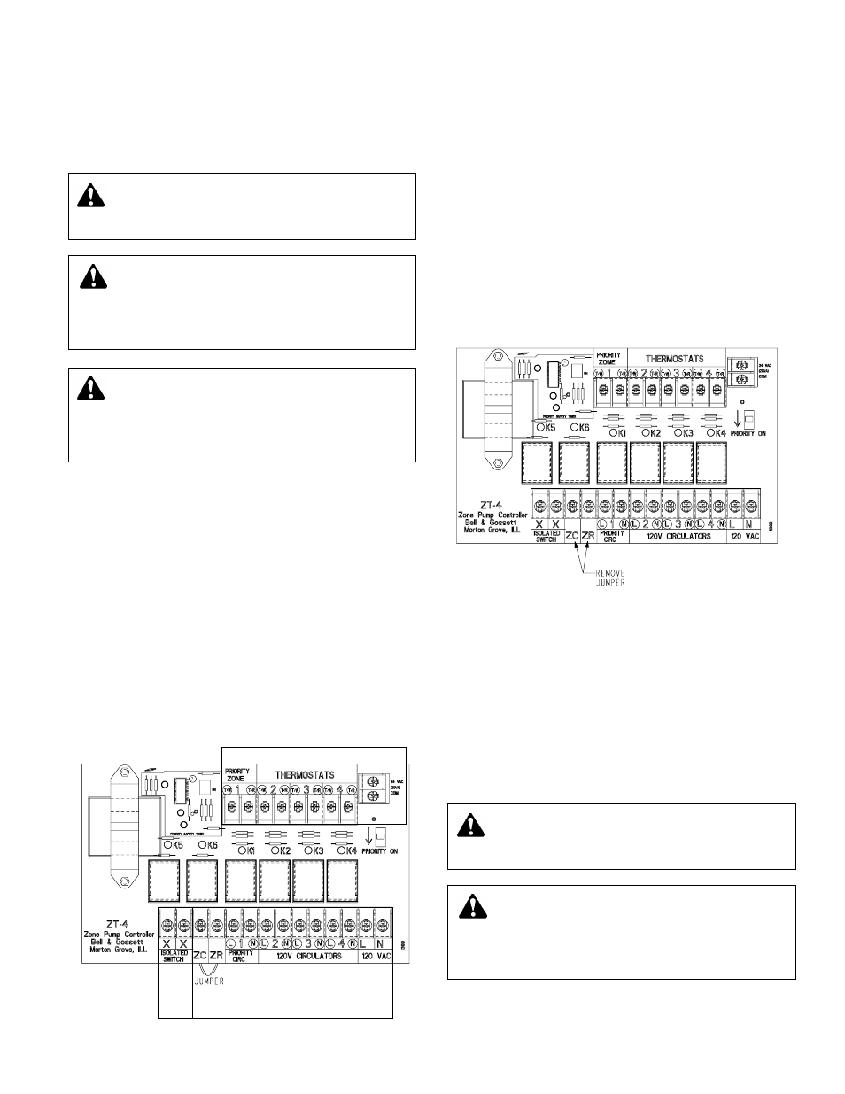
“Cold Start” Boiler Applications
The “cold start” boiler application provides circulator operation
whenever a zone thermostat calls for heat (regardless of boiler
water temperature) and will start the burner when used in con-
junction with an isolated end switch connected to the aquastat
on the boiler.
1) A factory installed jumper is connected between the ZC/ZR
terminals. Leave the jumper in its current position.
2) Attach the low voltage SPST thermostat leads to the
respective thermostat teminals.
3) Attach circulator leads to respective terminals.
4) Connect supply voltage line to the terminals marked 120
VAC, located on the lower right side of the circuit board.
5) Connect isolated switch (terminals XX) to TT terminals on
boiler aquastat. Note: The required aquastat connections
may vary, depending on model. Refer to aquastat manufac-
turers’ instructions to ensure appropriate interconnections.
2
WARNING: Electrical shock and potential circuit
damage. Disconnect power supply before beginning
installation. Failure to follow these instructions could result
in serious personal injury or death and property damage.
WARNING: Improper wiring and wire can cause elec-
trical shock and fires. Wiring connections must be
made in accordance with all applicable electrical codes and
ordinances. Use copper wire only. Failure to follow these
instructions could result in serious personal injury or death
and property damage.
Class 2 Terminals
Primary Terminals
Class 2
Te
rminals
JUMPER
WARNING: Electrical shock and potential circuit
damage. Disconnect power supply before beginning
installation. Failure to follow these instructions could result
in serious personal injury or death and property damage.
WARNING: Improper wiring and wire can cause elec-
trical shock and fires. Wiring connections must be
made in accordance with all applicable electrical codes and
ordinances. Use copper wire only. Failure to follow these
instructions could result in serious personal injury or death
and property damage.
WARNING: Potential electrical overload. Each circuit
is limited to a maximum of 10 amps and
1
/
3
HP. The
combined load for the controller is limited to 20 amps and
1 HP maximum. Failure to follow these instructions could
result in serious personal injury or death and property
damage.
“Tankless Coil” Boiler Applications
The “tankless coil” boiler application activates the boiler and
permits circulator operation only after boiler water has reached
the low temperature limit settings. If boiler temperatures drop
below the low limit setting, all circulators will cease operation
until the low limit temperature of the boiler is satisfied.
1) A factory installed jumper is connected between the ZC/ZR
terminals. Remove the jumper.
2) Connect the ZC/ZR terminals to the corresponding ZC/ZR
terminals on the boiler aquastat. The XX terminals are not
used. Note: The required aquastat connections may vary,
depending on model. Refer to aquastat manufacturers'
instructions to ensure appropriate interconnections
3) Attach the low voltage SPST thermostat leads to the
respective thermostat teminals.
4) Attach circulator leads to respective terminals.
5) Connect supply voltage line to the terminals marked 120
VAC, located on the lower right side of the circuit board.
Priority
If the priority switch is in the ON position, Zone 1 is the priority
zone. When the priority zone 1 circulator is actuated, the other
circulators will not operate. The ZoneTrol has a 30 minute
timer on the priority zone. After 30 minutes of continous oper-
ation, the priority zone function will default allowing all zones
to operate preventing possible house freeze up. The timer is
automatically reset after the priority zone is satisfied.
If the priority switch is not in the ON position, all zones operate
independent of each other.
ELECTRICAL INSTALLATION INSTRUCTIONS
FOR MODELS ZT-2 AND ZT-3