Bell & Gossett G10047E Circuit Setter Balance Valves 4” thru 12” sizes User Manual
Page 2
WARNING: Hot water leakage can occur from readout valve during probe insertion and during hook up of readout
kit. Follow the instruction manuals supplied with readout probes and readout kits for safe use. Failure to follow
these instructions could result in serious personal injury and/or property damage.
IMPORTANT: If the system contains a liquid with a specific gravity and/or viscosity higher or lower than that of water,
apply the appropriate correction factor noted in these instructions to obtain the actual GPM for the system liquid.
CAUTION: Avoid excessive pressure drop. Do not throttle Circuit Setter to pressure drops above 25 ft. of H2O (7.6m
of water). Failure to follow this instruction may result in valve noise and valve damage which can result in additional
property damage.
IMPORTANT: If balancing at less than 50% stem rise position is required, and this is the primary balance valve, Bell
& Gossett recommends that the impeller be sized to produce design flow. This will reduce electrical energy
consumption.
WARNING: Hot water leakage can occur from readout valve during probe insertion and during hook up of readout
kit. Follow the instruction manuals supplied with readout probes and readout kits for safe use. Failure to follow this
instruction could result in serious personal injury and/or property damage.
CAUTION: Avoid excessive pressure drop. Do not throttle Circut Setter to pressure drops above 25ft. of H
2
O (7.6m of
water). Failure to follow this instruction may result in valve noise and damage which can result in property damage.
IMPORTANT: If balancing at less than 50% stem rise position is required, and this is the primary balance valve, Bell &
Gossett recommends that the impeller be sized to produce design flow. This will reduce electrical energy consumption.
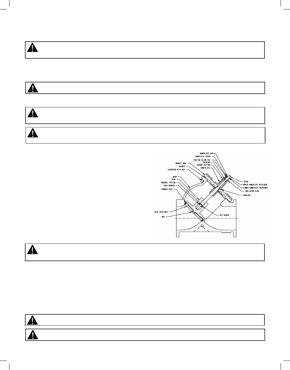
Fig. 1
2.Energize the zone, circuit and/or system pump(s) as applicable so that fluid is flowing through the Circuit Setter.
3.Using Bell & Gossett model RP-250B readout probes, attach a Bell & Gossett differential pressure readout kit to the readout
valves on Circuit Setter balance valve.
4.Read the differential pressure across the Circuit Setter.
5.Refer to the 100% open pressure drop curve in the Curve Booklet for the size Circuit Setter installed and read the flow
corresponding to the measured pressure drop. The Cv shown on the curve may also be used to calculate the flow or to read the
flow from scale 5 on the Bell & Gossett System Syzer.
6.If the GPM does not agree with the specified (required) GPM, close the Circuit Setter accordingly. Repeating steps 5 and 6
until the required results have been achieved.
How to use the Memory Stop Feature
1.After the final adjustment of the Circuit Setter has been made,
loosen the memory stop locking screw.
2.Position the memory stop so that it is as far up on the Circuit
Setter stem as it will go.
3.Tighten memory stop locking screw.
4.Circuit Setter can now be closed for system service and then
returned to its present position after service has been completed.
How to use Bell & Gossett Circuit Setters to Proportionally
Balance a System
1.Open fully all Circuit Setters on a single pump system.
2.If more than one branch circuit is used, start the balance
procedure by reading all of the flows to the units in a branch.
Each unit (coil) should have its own Circuit Setter for flow
balancing. Using Bell & Gossett PR-250B readout probes,
sequentially attach a Bell & Gossett differential pressure Readout
Kit to the Readout Valves on each Circuit Setter Balance Valve. Refer
to the Curve Booklet to obtain flow based on pressure drop.
3.Calculate the ratio of the actual flow to the design flow for each unit in the branch. This is the proportional flow rate.
(Actual flow divided by design flow).
4.Select the Circuit Setter with the lowest proportional flow. This Circuit Setter is left in the full open position. Every other
Circuit Setter in the branch is then reset to the same proportional flow.
5.If there are additional branches, repeat the steps in 3 and 4 above for each branch.
6.After all branches have been proportionately balanced, measure the full open flows on the Circuit Setter Balance Valves
installed on the risers. Calculate the proportional ratio of each riser Circuit Setter and select the one with the lowest
proportional ratio. This Circuit Setter is left fully open and the other riser Circuit Setters are adjusted to this same ratio.
7.Adjust pump flow so that circuits are receiving their design flow. This can be accomplished by adjusting a Circuit Setter
Balance Valve installed on the pump discharge or by changing the pump impeller size.