Xylem AC8584C Series HSCS Base Mounted Centrifugal Pumps User Manual
Page 8
8
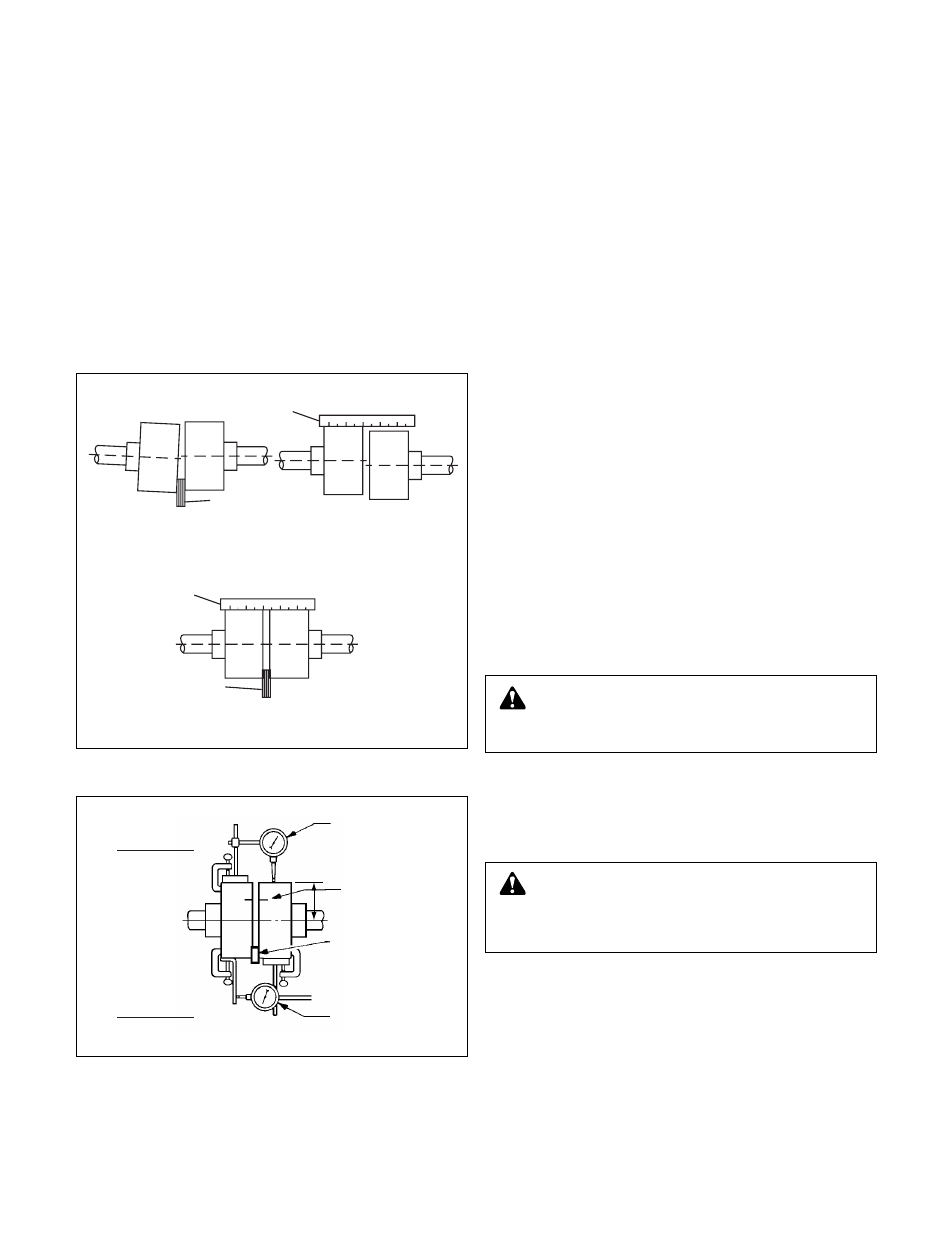
Method 1 – Using Straight Edge & T
aper Gauges
or Feelers
(See Figur
e 6A)
Proceed with this method only if satisfied that face and out-
side diameters of the coupling halves are square and concen-
tric with the coupling borers. If this condition does not exist or
elastomeric couplings do not make this method convenient,
use Method 2.
1. Check angular misalignment using a micrometer or caliper.
Measure from the outside of one flange to the outside of
the opposite flange at four points 90° apart. DO NOT
ROTATE COUPLER. Misalignment up to
1
/
64
" per inch of
coupler radius is permissible.
2. At four points 90° apart (DO NOT ROTATE COUPLER),
measure the parallel coupler misalignment by laying a
straight edge across one coupler half and measuring the
gap between the straight edge and opposite coupler half.
Up to a
1
/
64
" gap is permissible.
Method 2 – Using Dial Indicators (Figur
e 6B)
a. Make sure each hub is secured to its respective shaft and
that all connecting and/or spacing elements are removed at
this time.
b. The gap between the coupling hubs is set by the manufac-
turer before the units are shipped. However, this dimension
should be checked. (Refer to the coupling manufacturer’s
specifications supplied with the unit.)
c. Scribe index lines on coupling halves as shown in Figure
6B.
d. Mount dial indicator on one hub as shown for parallel align-
ment. Set dial to zero.
e. Turn both coupling halves so that index lines remain
matched. Observe dial reading to see whether driver needs
adjustment (See paragraph i below).
f. Mount dial indicator on one hub as shown for angular align-
ment. Set dial to zero.
g. Turn both coupling halves so that index lines remain
matched. Observe dial reading to see whether driver needs
adjustment (See paragraph i below).
h. Assemble coupling. Tighten all bolts and set screw(s). It
may be necessary to repeat steps c through f for a final
check.
i. For single element couplings, a satisfactory parallel mis-
alignment is .004"T.I.R., while a satisfactory angular mis-
alignment is .004"T.I.R. per inch of radius R (See Figure 6B).
Final Alignment
Final alignment cannot be accomplished until the pump has
been operated initially for a sufficient length of time to attain
operating temperature. When normal operating temperature
has been attained, secure the pump to re-check alignment
and compensate for temperature accordingly. See Alignment
Section.
OPTIONAL Alignment Pr
ocedure
If desir
ed, the pump and motor feet can be doweled to the
base after final alignment is complete. This should not be
done until the unit has been run for a sufficient length of time
and alignment is within the tolerance. See Doweling Section.
NOTE: Pump may have been doweled to base at factory
.
STRAIGHT EDGE
FEELER GAGE
FEELER GAGE
ANGULAR ALIGNMENT
PARALLEL ALIGNMENT
CORRECT ALIGNMENT
STRAIGHT EDGE
INCORRECT ALIGNMENT
FIGURE 6A – CHECKING ALIGNMENT (METHOD 1)
FIGURE 6B – CHECKING ALIGNMENT (METHOD 2)
DIAL
INDICATOR
INDEX LINE
R
RESILIENT
SEPARATOR
DIAL
INDICATOR
PARALLEL
ALIGNMENT
ANGULAR
ALIGNMENT
WARNING: Rotating Components Hazard
Do not operate pump without all guar
ds in place.
Failure to follow these instructions could result in serious
personal injury or death and property damage.
CAUTION:
Extreme Temperature and/or
Flying Debris Hazard
Eye pr
otection and gloves required. Failure to follow these
instructions could result in property damage and/or moder-
ate personal injury.