Xylem AC8584C Series HSCS Base Mounted Centrifugal Pumps User Manual
Page 28
2
nÊ
To install the oil ring, place the oil ring in the bearing housing
Ê
directly under the pipe plug hole. Run a wire through the pipe
Ê
plug hole, around the oil ring and back through the pipe plug
Ê
hole once again. Tie the wire to a metal washer (being a larger
Ê
diameter then the hole) causing the oil ring to become tight
Ê
against the inside top of the bearing housing. Then assemble
Ê
the bearing housing over the bearing. Untie the wire and the
Ê
oil ring will drop down onto the shaft. Check the position of
Ê
the oil ring through the pipe plug hole at the top of the bearing
Ê
housing. The oil ring must be resting on the shaft for correct
Ê
operation. A screwdriver can be used to correct the oil ring
Ê
position, if required.
Ê
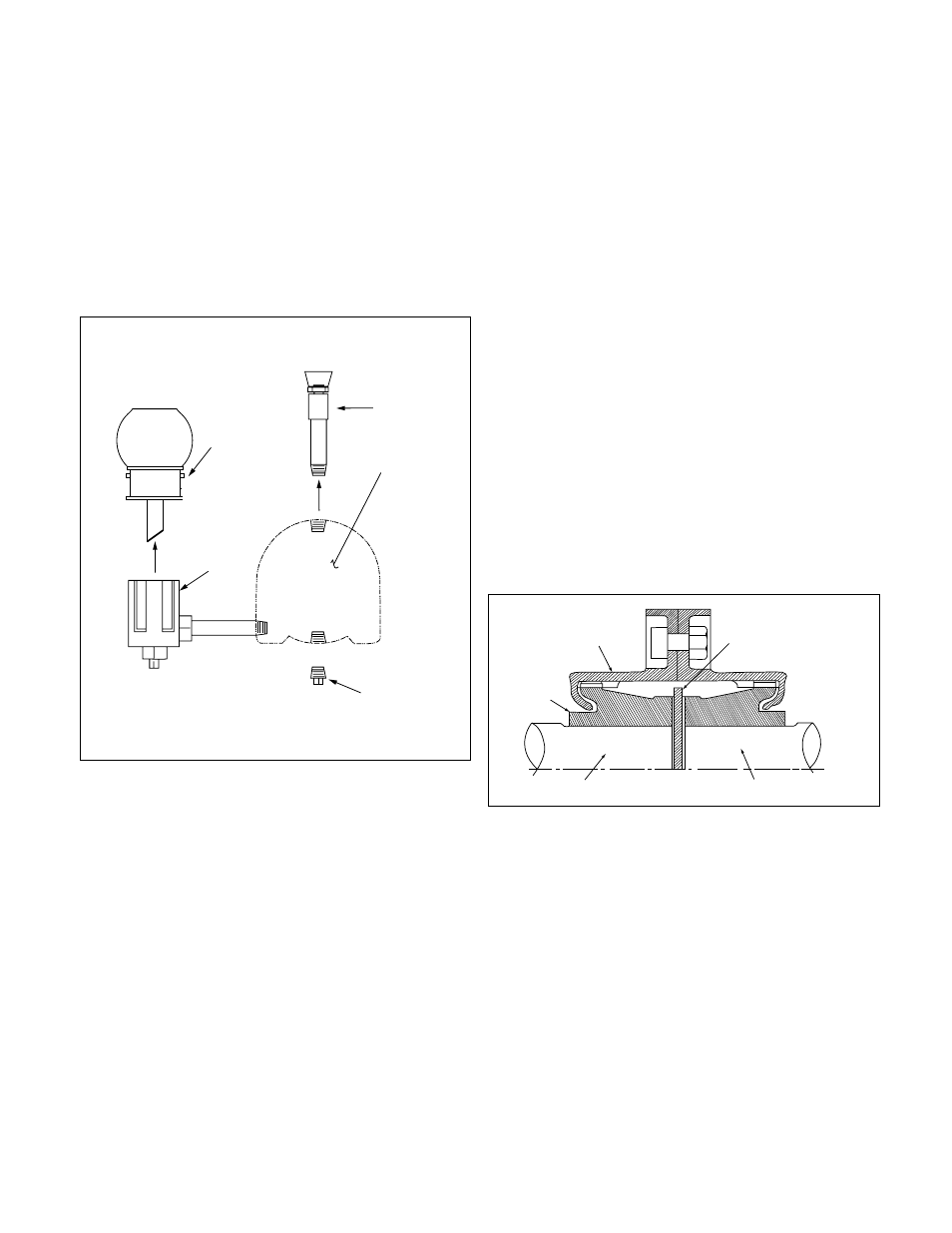
The following steps describe how to change the oil for oil
Ê
lubricated bearings. Figure 27 shows a typical oiler assembly.
Ê
1. Remove the vent assembly from the top of the bearing
Ê
housing.
Ê
2. Remove the pipe plug from the bottom of the bearing
Ê
housing.
Ê
3. Unscrew the reservoir and remove.
Ê
4. Flush the oiler and bearing housing with a light grade of
Ê
oil. Flush until all foreign particles have been removed.
Ê
5. Screw the pipe plug and vent assembly back into place.
Ê
6. Fill the reservoir with a good grade of filtered mineral oil.
Ê
Refer to oil lubrication instructions given previously in this
Ê
manual for type of oil.
NOTE: Y
ou must fill through Trico reservoir.
Ê
7. Place thumb over reservoir spout, invert and place reser-
Ê
voir on lower casting while removing thumb. Allow reser-
Ê
voir to empty, filling the bearing housing. Several fillings
Ê
of the reservoir may be required before the actual level is
Ê
reached, no more oil will run out of the reservoir.
Ê
8. When reservoir stays full, screw reservoir back into lower
Ê
casting.
Ê
Aperiodic filling of the reservoir is required. When the oil
Ê
becomes dirty, repeat steps 1 through 8.
Ê
LIMITED END FLOA
T COUPLING
For units with drivers having sleeve bearings the coupling
Ê
halves are set to limited total shaft axial movement to less
Ê
than one-half of the motor rotor assembly end float. This is
Ê
accomplished by inserting a phenolic disc, or equivalent, of a
Ê
specified thickness between the motor and pump shaft (See
Ê
Figure 28).
Ê
Most HSCS pumps installations use the all metal, gear type
Ê
coupling. Where limited end float gear type couplings are
Ê
used, the coupling hubs are slip-fit onto the pump and motor
Ê
shafts. After installation of the coupling covers and hubs; with
Ê
the motor set on its Magnetic Center, butt the pump and
Ê
motor shafts with the phenolic disc inserted between them.
Ê
(The pump thrust bearing limits end float towards the motor.)
Ê
The thrust bearing of the pump is large enough to carry any
Ê
magnetic thrust developed by the motor when aligned prop
Ê
erly.
Ê
Once the above instructions have been followed out com-
Ê
pletely, the
Alignment Pr
ocedures
starting on page 6 should
Ê
be followed.
Ê
FIGURE 28 – LIMITED END FLOA
T
COUPLING ARRANGEMENT
COVER
HUB
MOTOR SHAFT
PUMP SHAFT
PHENOLIC DISC
FIGURE 27 – OILER ASSEMBLY
RESERVOIR
LOWER
CASTING
VENT
ASSEMBLY
BEARING
HOUSING
PIPE
PLUG