Xylem AC8584C Series HSCS Base Mounted Centrifugal Pumps User Manual
Page 21
2
£
6. Place the sleeve O-ring (3-914-9) onto the shaft, into the
Ê
sleeve counterbore. Verify that Dimension “A” (Figure 12) is
Ê
maintained, then using a pin spanner wrench and hammer,
Ê
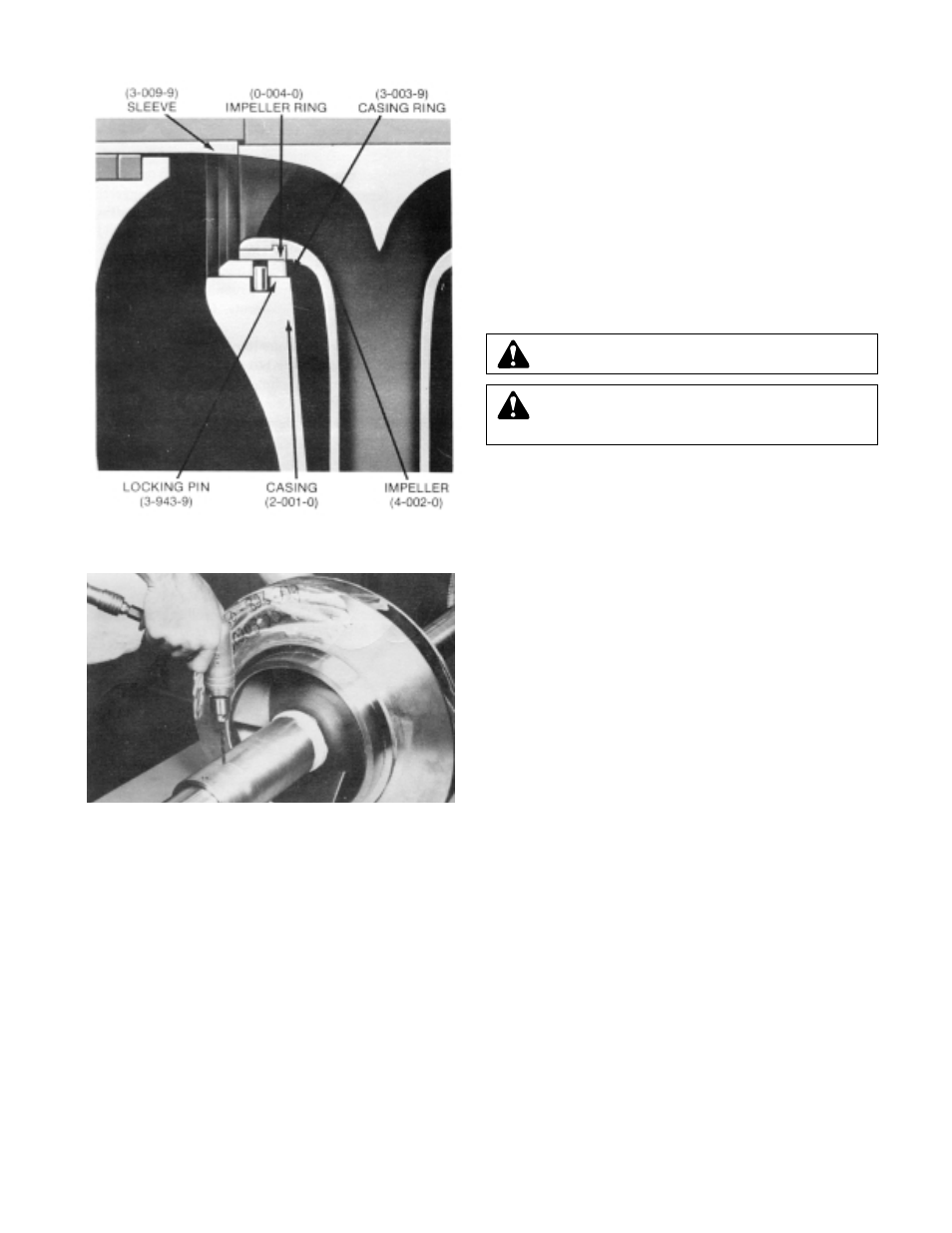
securely tighten the shaft sleeve nuts (3-015-9). Then, drill
Ê
a shallow recess in the shaft through the set screw hole in
Ê
each of the shaft sleeve nuts. Lock each shaft sleeve nut
Ê
in position with cup point set screws (3-902-9). (See Figure
Ê
15) A low strength sealant, such as Loctite 271, can be
Ê
used to retain set screws.
Ê
7. Assemble casing rings (3-003-9). (See page 26 for
Ê
adjustable rings.)
Ê
8. Start heating bearings (3-026-2) so that they will be ready
Ê
when called for in step 11. Use dry heat from induction
Ê
heat lamps from electric furnace, or a 10-15% soluble oil
Ê
and water solution.
Ê
9. Assemble oil seals (3-177-9) in each bearing cover. Install
Ê
gaskets (3-409-9) on each bearing cover.
Ê
NOTE: Seal lip or pr
essure side of oil seal must point
Ê
towards the end of the shaft that the oil seal is assembled
Ê
on. (See Figures 25 and 26)
Ê
10. Slide deflectors (3-136-9) and bearing covers (3-018-3, -4)
Ê
on the shaft. Install snap rings (3-915-9). Install thrust
Ê
washer (3-078-9) on the outboard end.
Ê
For ease of assembly and protection of rubber parts while
Ê
sliding rubber parts onto shaft, cover O-ring groove, key-
Ê
ways, and thread with electric tape.
Ê
NOTE: Inboar
d bearing cover (3-018-3) is approximately
Ê
1/4 inch less in width than the outboard bearing cover
Ê
(3-517-4). This is the only dimensional difference.
Ê
11. Press heated bearing (3-026-2) on shaft against snap ring
Ê
or thrust washer. Install locknut (3-516-4) and lockwasher
Ê
(3-517-4) on outboard end. Make certain locknut is
Ê
secured and then bend over tab on lockwasher.
Ê
12.
PUMPS WITH GREASE LUBRICA
TION
Cool bearings at r
oom temperature and coat with 2 or 3
Ê
ounces of a recommended grease.
Ê
PUMPS WITH OIL LUBRICA
TION
Refer to page 26 for installation of oil lubricated parts.
Ê
13. Assemble oil seals (3-177-9) in each bearing housing.
Ê
Refer to
NOTE under number 9 above for dir
ection of oil
Ê
seal.
Ê
14. Slide bearing housings (3-025-2) onto shaft (3-007-0) over
Ê
bearings (3-0262).
Ê
CAUTION: DO NOT
EXCEED 275°F.
Ê
CAUTION: These ar
e precision, high quality bearings.
Ê
exercise care at all times to keep them clean and free
Ê
from foreign matter.
Ê
FIGURE 14 – CASING AND IMPELLER RINGS
FIGURE 15 – DRILLING SET SCREW RECESS