Xylem AC8584C Series HSCS Base Mounted Centrifugal Pumps User Manual
Page 24
2
{Ê
(See Appendix “A” for exploded view.)
Ê
1. Close valves on suction and discharge sides of pump. If
Ê
no valves have been installed, it will be necessary to drain
Ê
the system.
Ê
2. Remove the coupler guard. Refer to section titled “Hex
Ê
Coupler Guard Removal/Installation.
Ê
3. Loosen the capscrews which secure the coupler flanges
Ê
to the coupler hubs. Remove the coupler flanges and
Ê
sleeve by compressing the flanges and pulling out from
Ê
beneath the hubs or by loosening the allen set screws and
Ê
sliding the hubs back on the shafts. Remove the coupler
Ê
hub from the pump shaft.
Ê
4. Drain the pump by opening vent plug (0-910-0) and
Ê
remove drain plugs (0-910-0) on suction and discharge
Ê
nozzle.
Ê
5. Remove seal lines (0-901-0, 0-950-0, 0-952-0), if supplied.
Ê
6. Remove gland bolts (3-904-9) and slide gland (3-014-2)
Ê
away from casing.
Ê
7. Remove all casing main joint cap screws (2-904-1) and
Ê
dowels (2-916-9). Use slot in casing main joint and sepa-
Ê
rate the casing halves with a pry bar. Lift upper half casing
Ê
(2-001-7) by cast lugs.
Ê
8. Remove cap screws (1-904-9) which hold bearing
Ê
housings (3-025-2) to the casing and lift rotating element
Ê
out of lower casing (2-001-08). Rotating element may now
Ê
be moved to a suitable working location.
Ê
9. Pull coupling half and key (3-911-2) off shaft (3-007-0).
Ê
NOTE: A spar
e rotating element can be installed at this
Ê
point.
Ê
10. Remove cap screws (3-904-9) from bearing covers (3-018-3,
К
-4).
К
11. Remove bearing housings (3-025-2), locknut (3-516-4),
Ê
and lockwasher (3-517-4). Mount bearing puller and
Ê
remove bearings (3-026-2). Remove thrust washer (3-078-9)
Ê
and snap ring (3-915-9).
Ê
NOTE: Locknut, lockwasher
, and thrust washer are not
Ê
used on inboard side.
12. Remove bearing covers (3-018-5, -4) and push oil seals
Ê
(3-177-9) out of bearing covers and coupling and bearing
Ê
housing. Pull deflectors (3-136-9) off shaft.
Ê
13. Remove glands (3-014-2). Loosen set screws and remove
Ê
mechanical seal head assembly (3-402-0). Press mechan
Ê
ical seal seats (3-401-0) from glands.
Ê
14. Remove casing rings (3-003-9) from impellers (4-002-0).
Ê
15. Remove set screw (3-902-9) from shaft nuts. Remove
Ê
shaft nuts (3-015-9), O-rings (3-914-9), sleeves (3-009-9),
Ê
sleeve gaskets (1-428-1), and impeller (4-002-0).
Ê
NOTE: Apply heat uniformly to the shaft sleeve to loosenÊ
the sealant between the shaft and sleeve.
Ê
To further assist in removing the sleeves, hold the shaft
Ê
vertically and drop it on a block of wood. The impeller
Ê
weight should force both the impeller and sleeve from the
Ê
shaft.
Ê
16. Refer to page 26 if pump is equipped with adjustable
Ê
rings.
Ê
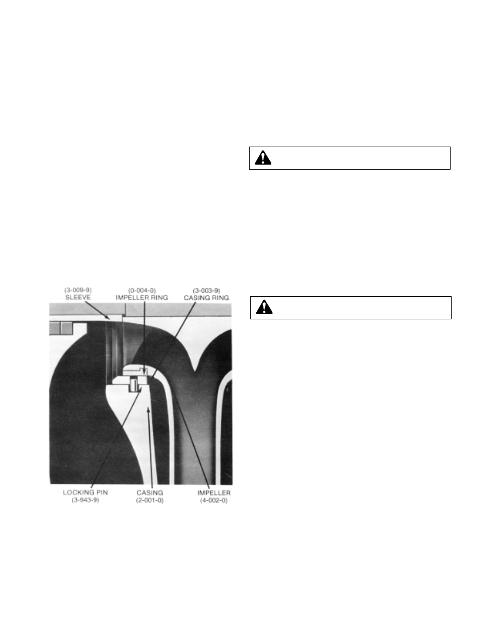
NOTE: For impellers with r
eplaceable rings - remove the
Ê
rings (4-004-9) by cutting the rings with a cold chisel. (See
Ê
Figure 20)
Ê
FIGURE 20 – CASING AND IMPELLER RINGS
CAUTION:
DO NOT REUSE THE BALL BEARINGS.
Ê
CAUTION:
DO NOT EXCEED 275ºF
.
К