Operating sequence – Bell & Gossett 210668B Z-4M User Manual
Page 2
• The sensor should be installed at an elevation above the
ground that will prevent accidental damage or tampering.
• Connect 18 AWG or similar wire to the two terminals pro-
vided in the enclosure and run the wires from the sensor to
the control as shown in Figure 2. Do not run the wires paral-
lel to telephone or power cables. If the sensor wires are
located in an area with strong sources of electromagnetic
interference (EMI), shielded cable or twisted pair should be
used or the wires can be run in a grounded metal conduit. If
using shielded cable, the shield wire should be connected
to the Com Sen terminal on the control and not to earth
ground.
• Replace the front cover of the sensor enclosure.
Water Temperature Sensor
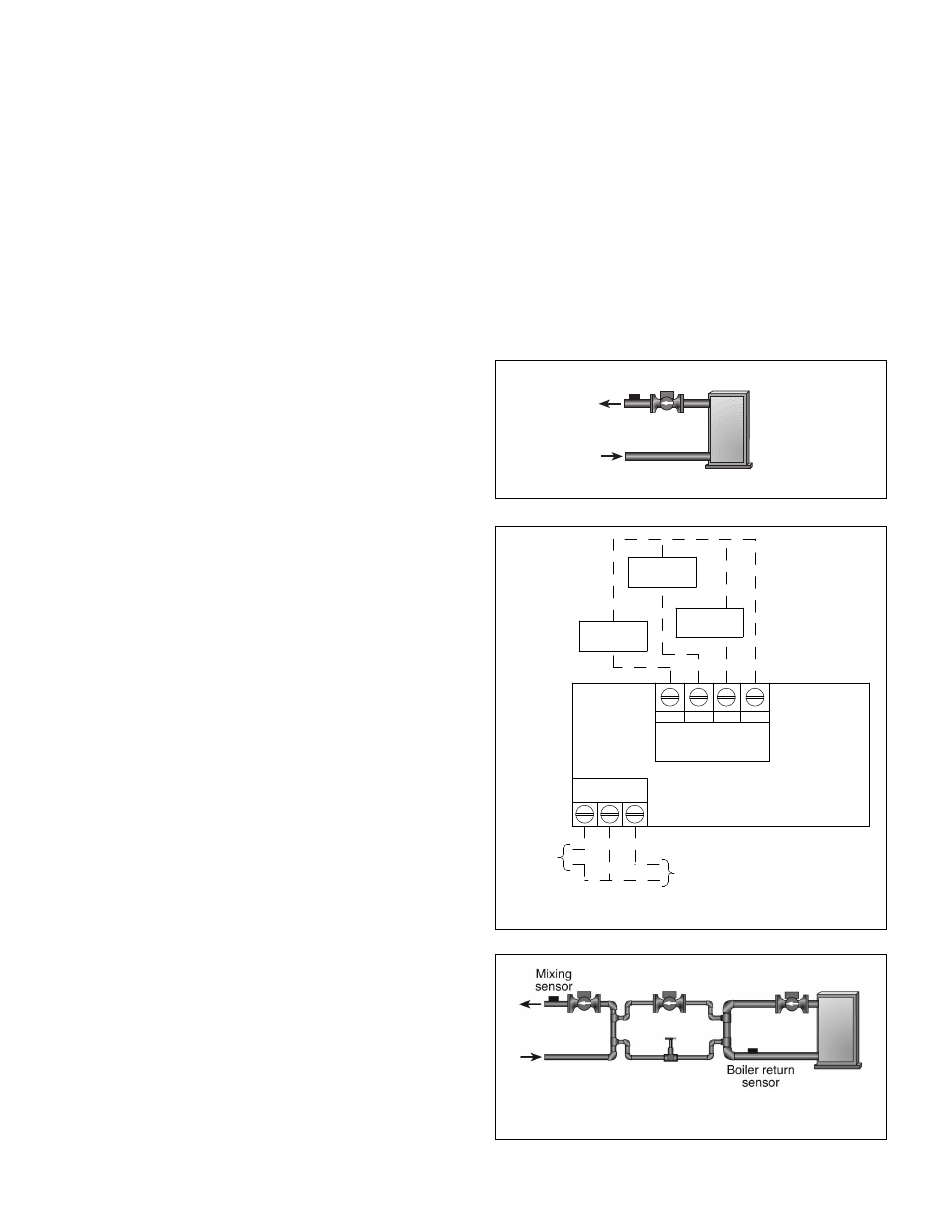
• Water temperature sensors should be located as shown in
Figures 1 (boiler reset) & 3 (mix reset).
• Sensor wiring is per Figure 2.
• The Water Temperature Sensor can be strapped directly to
the pipe using the cable tie provided. Insulation should be
placed around the sensor to reduce the effect of air currents
on the sensor measurement.
• The Water Temperature Sensor should be placed down-
stream of a pump or after an elbow or similar fitting. This is
especially important if large diameter pipes are used as the
thermal stratification within the pipe can result in erroneous
sensor readings. Proper sensor location requires that the
fluid is thoroughly mixed within the pipe before it reaches
the sensor.
OPERATING SEQUENCE
Boiler Reset Control
The Boiler Reset Control operates a single on / off heat source
to control the supply water temperature to a hydronic system.
The supply water temperature is based on the current outdoor
air temperature and the Characterized Heating Curve settings.
Outdoor Reset: The controller calculates a supply tempera-
ture based on the current outdoor air temperature and the
Characterized Heating Curve settings. The burner on the boiler
is then cycled to maintain the water temperature required
based on the heating curve.
Warm Weather Shutdown: When the outdoor air temperature
rises above the WWSD setting, the controller turns on the
WWSD segment in the display. When the control is in Warm
Weather Shut Down, the Boiler Demand pointer is displayed, if
there is a demand. However, the control does not operate the
heating system to satisfy this demand.
Mix Reset Control
The Mix Reset Control uses a variable speed injection pump
to control the supply water temperature to a hydronic system.
The supply water temperature is based on either the current
outdoor temperature, or a fixed setpoint.
Outdoor Reset: The controller calculates a mixing supply
temperature based on the current outdoor air temperature and
the Characterized Heating Curve settings.
Variable Speed Injection: circulator is connected to the con-
troller. The controller increases or decreases the power output
to a standard wet rotor circulator when there is a mixing
demand. The circulator speed varies to maintain the correct
mixed supply water temperature at the mix sensor. A visual
indication of the current variable speed output is displayed in
the LCD in the form of a horizontal bar graph.
Boiler Protection (BOIL MIN): The controller is capable of
providing boiler protection from cold mixing system return
water temperatures. If the boiler sensor temperature is cooler
than the BOIL MIN setting while the boiler is firing, the con-
troller reduces the output to the variable speed injection
pump. This limits the amount of cool return water to the boiler,
and allows the boiler temperature to recover.
Exercise: The controller has a built-in exercising function. If
the pump has not been operated at least once every 3 days,
the control turns on the output for 10 seconds. This minimizes
the possibility of the pump seizing during a long period of
inactivity.
Warm Weather Shutdown (WWSD)
When the outdoor air temperature rises above the WWSD set-
ting, the controller turns on the WWSD segment in the display.
When the control is in Warm Weather Shut Down, the Mixing
Demand pointer is displayed, if there is a demand. However,
the control does not operate the heating system to satisfy this
demand.
Boiler supply
sensor
BOIL OUT
SUP COM
Boiler Temp.
Sensor
Sensor
Temp. Sensor
Outdoor Temp.
Mix Supply
SYS/
BLR.
N
INJ/
MIX
120 VAC
To system
pump (if
applicable)
1/3 max.
HP*
To
injector
pump (if
applicable)
1.1A max.
Figure 1: Sensor Location for Boiler Reset
Figure 2: Sensor and Mix Pump Wiring
Figure 3: Pump Terminology and Sensor Location
on systems using Mix or Injection Pump
*Do not exceed the maximum combined load.