Precision timers, New prod uc t typical applications characteristics – Diodes NA555 User Manual
Page 8
NE555/SA555/NA555
PRECISION TIMERS
NE555/SA555/NA555
Document number: DS35112 Rev. 4 - 2
8 of 14
February 2012
© Diodes Incorporated
NEW PROD
UC
T
Typical Applications Characteristics
(cont.)
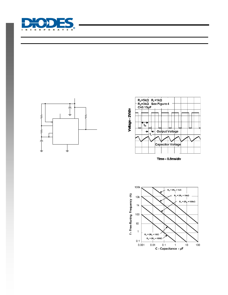
Astable Operation
As shown in Figure 4, adding a second resistor, R
B
, to the circuit of Figure 1 and connecting the trigger input to the threshold
input causes the timer to self-trigger and run as a multivibrator. The capacitor C charges through R
A
and R
B
and then
discharges through R
B
. Therefore, the duty cycle is controlled by the values of R
A
and R
B
.
This astable connection results in capacitor C charging and discharging between the threshold-voltage level (
≉0.67V
CC
) and
the trigger-voltage level (
≉0.33V
CC
). As in the monostable circuit, charge and discharge times (and, therefore, the frequency
and duty cycle) are independent of the supply voltage.
C
R
L
R
A
R
B
THRES
TRIG
DISCH
RESET
CONT
V
CC
GND
OUT
Output
4
7
6
2
1
3
8
5
Open
(See Note A)
V
CC
(5V to 15V)
Decoupling CONT voltage to ground with a capacitor can
improve operation. This should be evaluated for individual
applications.
0.01µF
Fig. 4 Circuit for Astable Operation
Fig. 5 Typical Astable Waveforms
Figure 5 shows typical waveforms generated during astable operation. The output high-level duration t
H
and low-level
duration t
L
can be calculated as follows:
t
H
= 0.693(R
A
+R
B
)C
t
L
= 0.693(R
B
)C
Other useful equations are:
period = t
H
+ t
L
= 0.693(R
A
+ 2R
B
)C
frequency = 1.44/(R
A
+ 2R
B
)C
output driver duty cycle = t
L
/(t
H
+ t
L
) = R
B
/(R
A
+ 2R
B
)
output waveform duty cycle = t
H
/(t
H
+ t
L
) = 1 – R
B
/(R
A
+ 2R
B
)
low to high ratio = t
L
/t
H
= R
B
/(R
A
+ R
B
)
Fig. 6 Free Running Frequency