Precision timers, New prod uc t electrical characteristics – Diodes NA555 User Manual
Page 4
NE555/SA555/NA555
PRECISION TIMERS
NE555/SA555/NA555
Document number: DS35112 Rev. 4 - 2
4 of 14
February 2012
© Diodes Incorporated
NEW PROD
UC
T
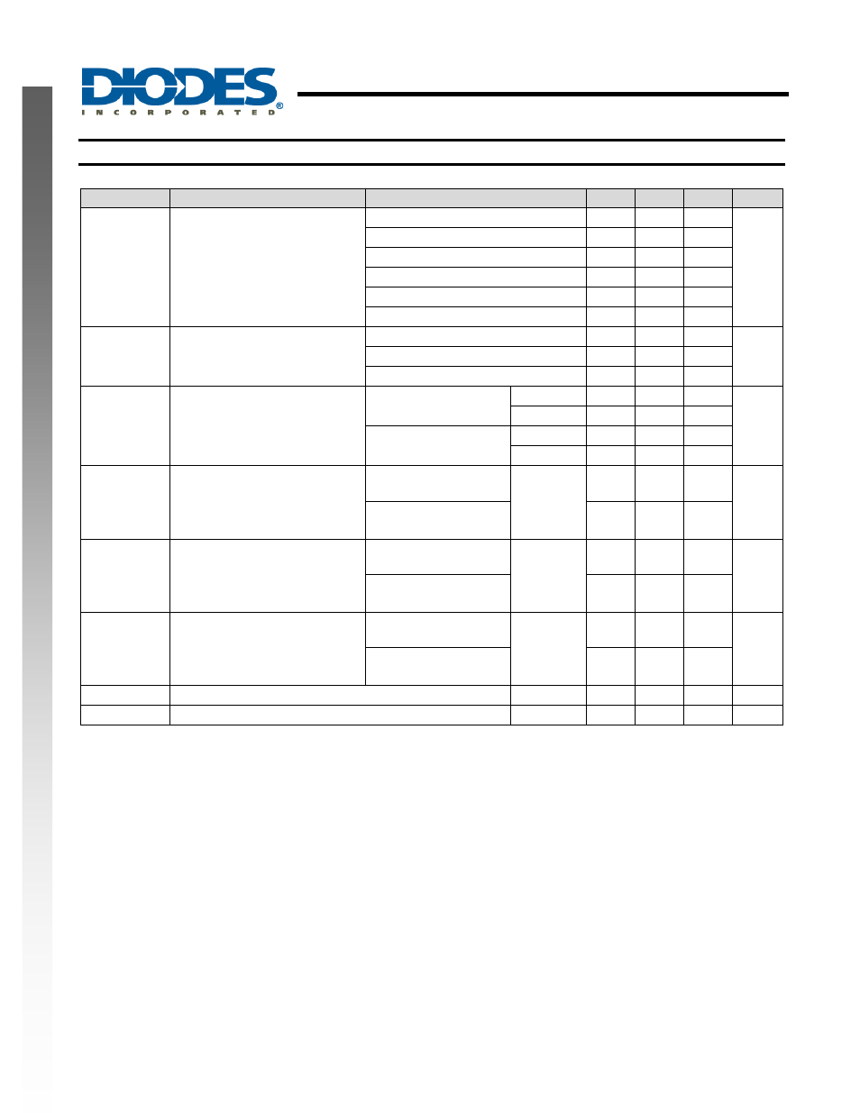
Electrical Characteristics
(V
CC
= 5V to 15V, T
A
= 25°C unless otherwise stated)
Symbol
Parameter
Test conditions
Min
Typ.
Max
Unit
V
OL
Low level output voltage
V
CC
= 15V, I
OL
= 10mA
0.1
0.25
V
V
CC
= 15V, I
OL
= 50mA
0.4
0.75
V
CC
= 15V, I
OL
= 100mA
2
2.5
V
CC
= 15V, I
OL
= 200mA
2.5
V
CC
= 5V, I
OL
= 5mA
0.1
0.35
V
CC
= 5V, I
OL
= 8mA
0.15
0.4
V
OH
High level output voltage
V
CC
= 15V, I
OH
= -100mA
12.75 13.3
V
V
CC
= 15V, I
OH
= -200mA
12.5
V
CC
= 5V, I
OH
= -100mA
2.75 3.3
I
CC
Supply current
Output low, no load
V
CC
= 15V
10
15
mA
V
CC
= 5V
3 6
Output high, no load
V
CC
= 15V
9
13
V
CC
= 5V
2 5
T
ER
Initial error of timing interval
(Note 8)
Each time, monostable
(Note 9)
1 3
%
Each time, astable
(Note 10)
2.25
T
TC
Temperature coefficient of timing
interval
Each time, monostable
(Note 9)
T
A
= full
range
50
ppm/°C
Each time, astable
(Note 10)
150
T
VCC
Supply voltage sensitivity of
timing interval
Each time, monostable
(Note 9)
0.1
0.5
%/V
Each time, astable
(Note 10)
0.3
T
RI
Output pulse rise time
C
L
= 15pF
100
300 ns
T
FA
Output pulse fall time
C
L
= 15pF
100
300 ns
Notes:
6. This parameter influences the maximum value of the timing resistors R
A
and R
B
in the circuit of Figure 12. For example, when V
CC
= 5 V, the
maximum value is R = R
A
+ R
B
≉ 3.4MΩ, and for V
CC
= 15 V, the maximum value is 10M
Ω.
7. No protection against excessive pin 7 current is necessary providing package dissipation rating is not exceeded
8. Timing interval error is defined as the difference between the measured value and the average value of a random sample from each process run.
9. Values specified are for a device in a monostable circuit similar to Figure 9, with the following component values: R
A
= 2k
Ω to 100kΩ, C = 0.1uF.
10. Values specified are for a device in an astable circuit similar to Figure 12, with the following component values: R
A
= 1k
Ω to 100kΩ, C = 0.1uF.