Pam8012, Application information – Diodes PAM8012 User Manual
Page 8
PAM8012
Document number: DSxxxxx Rev. 1 - 3
8 of 14
www.diodes.com
October 2012
© Diodes Incorporated
PAM8012
A Product Line of
Diodes Incorporated
Application Information
(cont.)
Input Capacitors (C
I
)
In the typical application, an input capacitor, C
i
, is required to allow the amplifier to bias the input signal to the proper DC level for optimum
operation. In this case, Ci and the minimum input impedance R
I
form is a high-pass filter with the corner frequency determined in the follow
equation:
C
R
2
1
f
I
I
C
Π
=
It is important to consider the value of CI as it directly affects the low frequency performance of the circuit. For example, the specification calls
for a flat bass response are down to 150Hz.
Equation is reconfigured as followed:
f
R
2
1
C
I
I
I
Π
=
When input resistance variation is considered, the C
I
is 34nF, so one would likely choose a value of 33nF. A further consideration for this
capacitor is the leakage path from the input source through the input network (C
I
, R
I
+ R
F
) to the load. This leakage current creates a DC offset
voltage at the input to the amplifier that reduces useful headroom, especially in high gain applications. For this reason, a low-leakage tantalum
or ceramic capacitor is the best choice. When polarized capacitors are used, the positive side of the capacitor should face the amplifier input in
most applications as the DC level is held at V
DD
/2, which is likely higher than the source DC level. Please note that it is important to confirm the
capacitor polarity in the application.
Decoupling Capacitor (C
S
)
The PAM8012 is a high-performance CMOS audio amplifier that requires adequate power supply decoupling to ensure the output total
harmonic distortion (THD) as low as possible. Power supply decoupling also prevents the oscillations causing by long lead length between the
amplifier and the speaker.
The optimum decoupling is achieved by using two different types of capacitors that target on different types of noise on the power supply leads.
For higher frequency transients, spikes, or digital hash on the line, a good low equivalentseries- resistance (ESR) ceramic capacitor, typically
1µF, is placed as close as possible to V
DD
pin for the best operation. For filtering lower frequency noise signals, a large ceramic capacitor of
10µF or greater placed near the audio power amplifier is recommended.
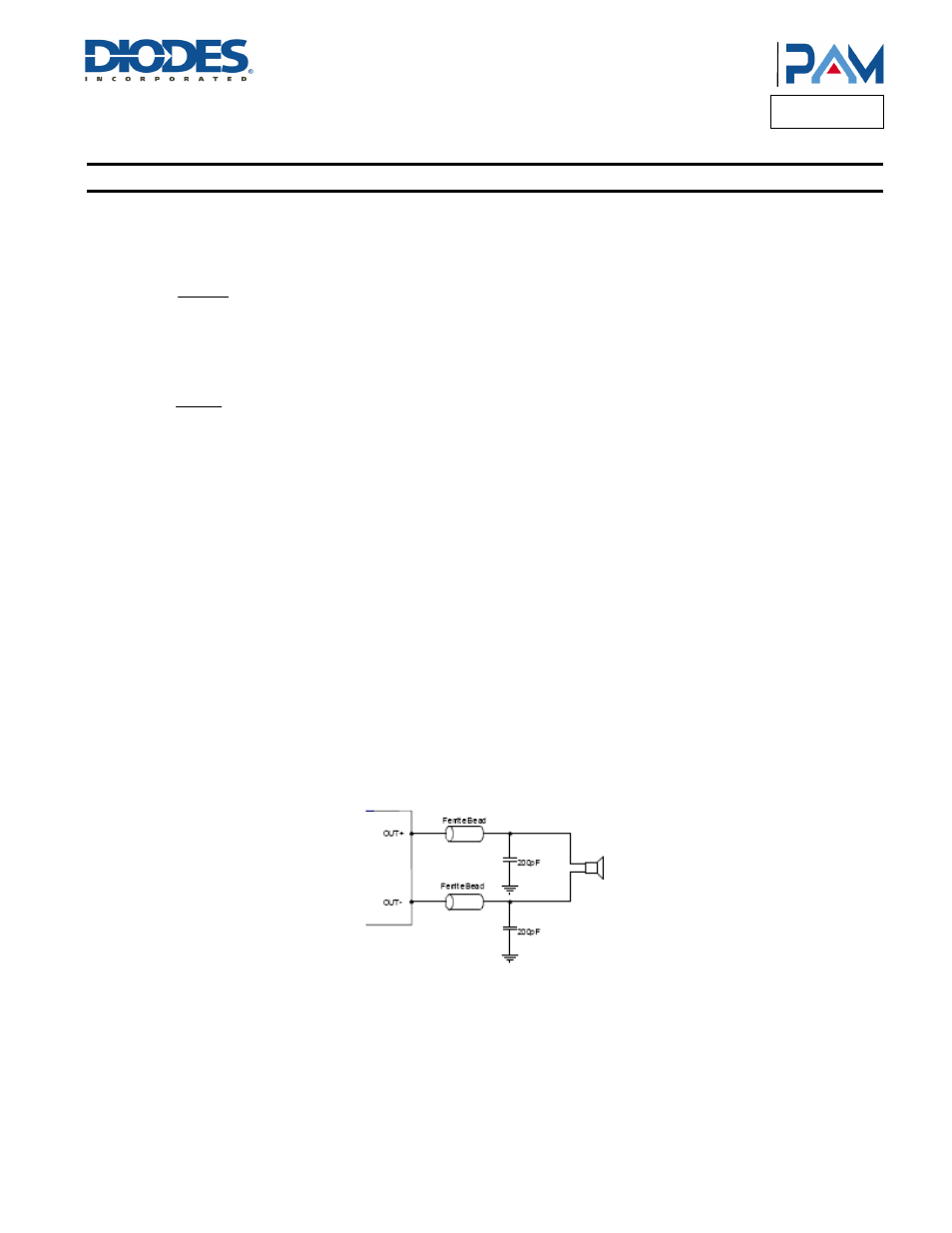
How to Reduce EMI
Most applications require a ferrite bead filter for EMI elimination shown at Figure 1. The ferrite filter reduces EMI around 1MHz and higher.
When selecting a ferrite bead, choose one with high impedance at high frequencies, but low impedance at low frequencies.
Figure 1: Ferrite Bead Filter to Reduce EMI
Shutdown Operation
In order to reduce power consumption while not in use, the PAM8012 contains shutdown circuitry that is used to turn off the amplifier’s bias
circuitry. This shutdown feature turns the amplifier off when logic low is placed on the EN pin. By switching the EN pin connected to GND, the
PAM8012 supply current draw will be minimized in idle mode.
Short Circuit Protection (SCP)
The PAM8012 has short circuit protection circuitry on the outputs to prevent the device from damage when output-to-output shorts or output-to-
GND shorts occur. When a short circuit occurs, the device immediately goes into shutdown state. Once the short is removed, the device will be
reactivated.