Pam2327, Recommended operating conditions, Thermal information – Diodes PAM2327 User Manual
Page 3: Electrical characteristics
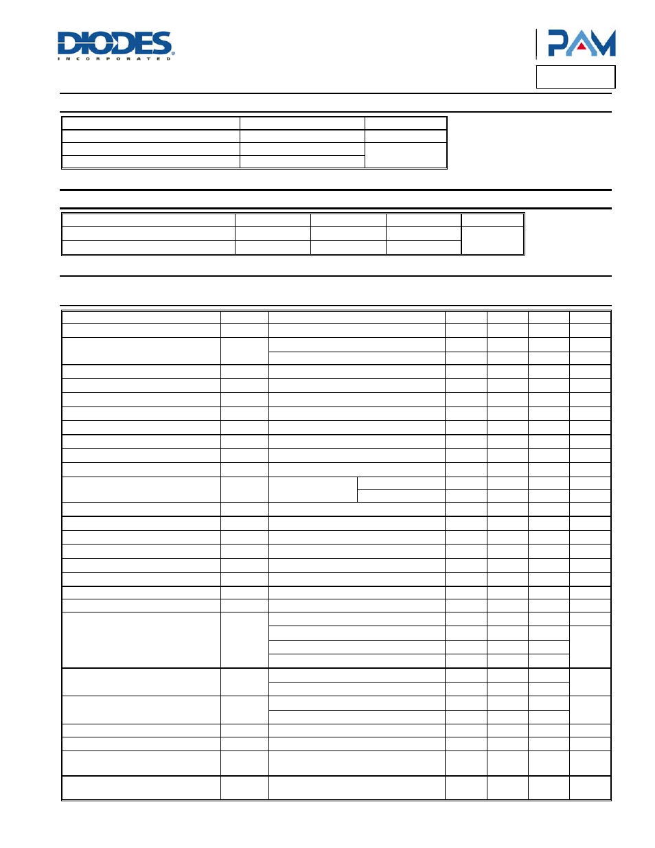
PAM2327
Document number: DS36277 Rev. 2 - 2
3 of 11
July 2013
© Diodes Incorporated
PAM2327
A Product Line of
Diodes Incorporated
Recommended Operating Conditions
(@T
A
= +25°C, unless otherwise specified.)
Parameter Rating
Unit
Supply Voltage
2.5 to 5.5
V
Operation Temperature Range
-40 to +85
°C
Junction Temperature Range
-40 to +125
Thermal Information
Parameter Symbol
Package
Max
Unit
Thermal Resistance (Junction to Case)
θ
JC
QFN2x2-12 16
°C/W
Thermal Resistance (Junction to Ambient)
θ
JA
QFN2x2-12 80
Electrical Characteristics
(@T
A
= +25°C, V
IN
= 3.3V, V
OUT
= 1.2V, C
IN
= 20µF, C
O
= 20µF, L = 1µH, unless otherwise specified.)
Parameter Symbol Test
Conditions Min
Typ
Max
Units
Input Voltage Range
V
IN
2.5 3.3 5.5 V
UVLO Threshold
V
UVLO
V
IN
Rising
2.35 2.5 2.65 V
Hysteresis
400
550
mV
Output Voltage Accuracy
V
OUT
-4.0
+4.0
%
Regulated Feedback Voltage
V
FB
No Load
0.591
0.60
0.609
V
PMOS Current Limit
I
LIM
4.8 A
Output Voltage Line Regulation
LNR
V
IN
= 3.3V to 5.5V
0.5 1
%/V
Output Voltage Load Regulation
LDR
I
O
= 1mA to 2A
2
%
Quiescent Current
I
Q
No Load
55
100
µA
Shutdown Current
I
SD
V
EN
= 0V
1
µA
Oscillator Frequency
f
OSC
1.0 1.2 1.6 MHz
Drain-Source On-State Resisitance
R
DS(ON)
I
DS
= 100mA
P MOSFET
40
70
m
Ω
N MOSFET
30
50
m
Ω
SW Leakage Current
I
LSW
1
µA
Start-Up Time
t
S
250
1000
µs
PSM Threshold
I
TH
V
IN
= 3.3V, V
O
= 1.2V
250
mA
EN Threshold High
V
EH
1.2 V
EN Threshold Low
V
EL
0.4
V
EN Input Current
I
EN
V
EN
= 2V
1.2 4 µA
Over Temperature Protection
OTP
150 °C
OTP Hysteresis
OTH
30 °C
Effciency
η
I
O
= 10mA
75 81
I
O
= 500mA to 1A
85 90
%
I
O
= 1.5A
85 90
I
O
= 2A
80 89
Output Ripple
Ripple
I
O
= 10mA
-5 +5
%
I
O
≥ 300mA
-2 +2
Output Transient Ripple
V
PK-PK
I
O
= 20mA to 1A
-10 +10
%
I
O
= 20mA to 2A
-12 +12
PG Pin Trigger Delay
90 µs
PG Pin Threshold (relative to V
OUT
)
±10 %
PG Open Drain Impedance
(PG = PV
IN
)
250K 500K
Ω
PG Open Drain Impedance
(PG = Low)
100
Ω