Diodes DLD101 User Manual
Dld101 new prod uc t, Features, Mechanical data
DLD101
Document number: DS32007 Rev. 8 - 2
1 of 9
April 2010
© Diodes Incorporated
DLD101
NEW PROD
UC
T
LINEAR MODE CURRENT SINK LED DRIVER
Features
•
Primarily Designed for Driving LED/s for Illumination, Signage
and Backlighting Applications
•
Ideally Suited for Linear Mode Constant Current Applications
•
V
BE
Referenced Current Sink Circuit
• Includes:
•
N-Channel Enhancement Mode MOSFET (Q1)
• Base
Accessible
Pre-Biased Transistor (Q2)
•
High Voltage Capable (50V)
•
Small Form Factor Surface Mount Package
• High
Dissipation
Capability
•
Low Thermal Resistance
•
Lead Free By Design/RoHS Compliant (Note 1)
•
"Green" Device (Note 2)
•
Qualified to AEC-Q101 Standards for High Reliability
Mechanical Data
• Case:
DFN3030D-8
•
Case Material: Molded Plastic, "Green" Molding Compound.
UL Flammability Classification Rating 94V-0
•
Moisture Sensitivity: Level 1 per J-STD-020
•
Terminals: Finish — NiPdAu over Copper leadframe. Solderable
per MIL-STD-202, Method 208
•
Marking Information: See Page 7
•
Ordering Information: See Page 7
•
Weight: 0.0172 grams (approximate)
Maximum Ratings: (Q1)
@T
A
= 25°C unless otherwise specified
Characteristic Symbol
Value
Unit
Drain Source Voltage
V
DSS
100 V
Gate-Source Voltage
V
GSS
±20
V
Drain Current (Note 3)
T
A
= 25°C
T
A
= 70°C
I
D
1.0
0.8
A
Drain Current (Note 3)
Pulsed
I
DM
3.0 A
Body-Diode Continuous Current (Note 3)
I
S
1.0 A
Maximum Ratings: (Q2)
@T
A
= 25°C unless otherwise specified
Characteristic Symbol
Value
Unit
Supply Voltage
V
CC
50 V
Input Voltage
V
IN
-5 to +30
V
Output Current (DC)
I
O
100 mA
Notes:
1. No purposefully added lead.
2. Diodes Inc.'s "Green" policy can be found on our webs
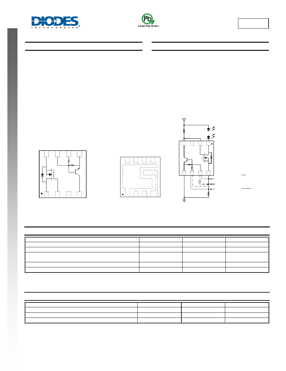
Top View
Internal Schematic
Top View
Package Pin-Out Configuration
Typical Application Circuit for Linear
Mode Current Sink LED Driver
8
7
6
5
1
2
3
4
D2
G2
NC
C1
S2
B1
B1’
E1
8
7
6
5
1
2
3
4
D2
G2
NC
C1
S2
B1
B1’
E1
Q2
Q1
R2
R1
8
7
6
5
1
2
3
4
C
E
B
G
D
S
R
C
R
S
Option 1
Option 2
Option 3
LED String
Option 3:
I
LED
≈
V
BE
R
S
Options 1 & 2:
I
LED
≈
1.1 V
BE
R
S
V
Supply
CC
Q2
Q1
V
DS
R2
R1
Option 2:
Capacitor is across R2 for
better noise performance.