Electrical characteristics – Diodes DXT5551P5 User Manual
Page 4
DXT5551P5
Document number: DS32066 Rev. 3 - 2
4 of 7
November 2010
© Diodes Incorporated
DXT5551P5
PowerDI is a registered trademark of Diodes Incorporated.
ADVAN
CE I
N
F
O
RM
ATI
O
N
A Product Line of
Diodes Incorporated
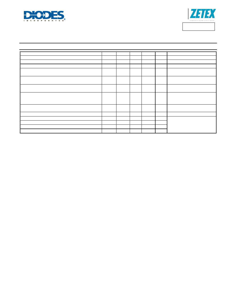
Electrical Characteristics
@T
A
= 25°C unless otherwise specified
Characteristic Symbol
Min
Typ
Max Unit
Test
Condition
Collector-Base Breakdown Voltage
BV
CBO
180 270
−
V
I
C
= 100
μA
Collector-Emitter Breakdown Voltage (Note 7)
BV
CEO
160 200
−
V
I
C
= 1mA
Emitter-Base Breakdown Voltage
BV
EBO
6.0 7.85
−
V
I
E
= 10
μA
Collector Cutoff Current
I
CBO
−
−
<1
−
50
50
nA
μA
V
CB
= 120V
V
CB
= 120V, T
A
= 100°C
Collector-Emitter Saturation Voltage (Note 7)
V
CE(sat)
−
−
65
115
150
200
mV
mV
I
C
= 10mA, I
B
= 1mA
I
C
= 50mA, I
B
= 5mA
Base-Emitter Saturation Voltage (Note 7)
V
BE(sat)
−
−
760
840
1000
1200
mV
mV
I
C
= 10mA, I
B
= 1mA
I
C
= 50mA, I
B
= 5mA
DC Current Gain (Note 7)
h
FE
80
80
30
130
145
65
−
250
−
−
V
CE
= 5V, I
C
= 1mA
V
CE
= 5V, I
C
= 10mA
V
CE
= 5V, I
C
= 50mA
Transition Frequency
f
T
−
130
−
MHz
V
CE
= 10V, I
C
= 10mA,
f = 100MHz
Output Capacitance (Note 7)
C
obo
−
−
6 pF
V
CB
= 10V, f = 1MHz
Delay Time
t
(d)
−
95
−
ns
V
CC
= 510V, I
C
= 10mA,
I
B1
= I
B2
= 1mA
Rise Time
t
(r)
−
64
−
Ns
Storage Time
t
(s)
−
1256
−
ns
Delay Time
t
(f)
−
140
−
ns
Notes:
7. Pulse Test: Pulse width
≤300μs. Duty cycle ≤2.0%.