Diodes DXT651 User Manual
Ce b, Dxt651, Features
DXT651
Document Number: DS31184 Rev: 5 - 2
1 of 6
February 2013
© Diodes Incorporated
DXT651
60V NPN LOW VCE(sat) TRANSISTOR IN SOT89
Features
BV
CEO
> 60V
I
C
= 3A high Continuous Current
Low saturation voltage V
CE(sat)
< 300mV @ 1A
Complementary PNP Type: DXT751
Totally Lead-Free & Fully RoHS compliant (Notes 1 & 2)
Halogen and Antimony Free. “Green” Device (Note 3)
Qualified to AEC-Q101 Standards for High Reliability
Mechanical Data
Case:
SOT89
Case material: Molded Plastic. “Green” Molding Compound.
UL Flammability Rating 94V-0
Moisture Sensitivity: Level 1 per J-STD-020
Terminals: Finish - Matte Tin Plated Leads, Solderable per
MIL-STD-202, Method 208
Weight: 0.052 grams (Approximate)
Ordering Information
(Note 4)
Product
Marking
Reel size (inches)
Tape width (mm)
Quantity per reel
DXT651-13 KN2
13
12
2,500
DXT651-13R KN2
13
12
4,000
Notes:
1. No purposely added lead. Fully EU Directive 2002/95/EC (RoHS) & 2011/65/EU (RoHS 2) compliant.
2. S more information about Diodes Incorporated’s definitions of Halogen and Antimony free, "Green"
and Lead-Free.
3. Halogen and Antimony free "Green” products are defined as those which contain <900ppm bromine, <900ppm chlorine (<1500ppm total Br + Cl)
and <1000ppm antimony compounds.
4. For packaging details, go to our website at
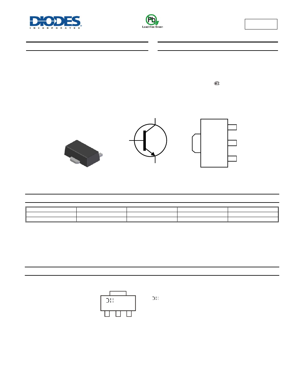
Marking Information
Top View
Device Symbol
Top View
Pinout
SOT89
KN2 = Product Type Marking Code
= Manufacturer’s Marking Code
YWW = Date Code Marking
Y = Last digit of year (ex: 7 = 2007)
WW = Week code (01 – 53)
C
E
B
C
E
C
B
KN2
YWW