New prod uc t parameter measurement information – Diodes 74LVCE1G06 User Manual
Page 7
74LVCE1G06
SINGLE INVERTER BUFFER/DRIVER WITH
OPEN DRAIN OUTPUT
74LVC1GE06
Document number: DS32273 Rev. 2 - 2
7 of 13
December 2010
© Diodes Incorporated
NEW PROD
UC
T
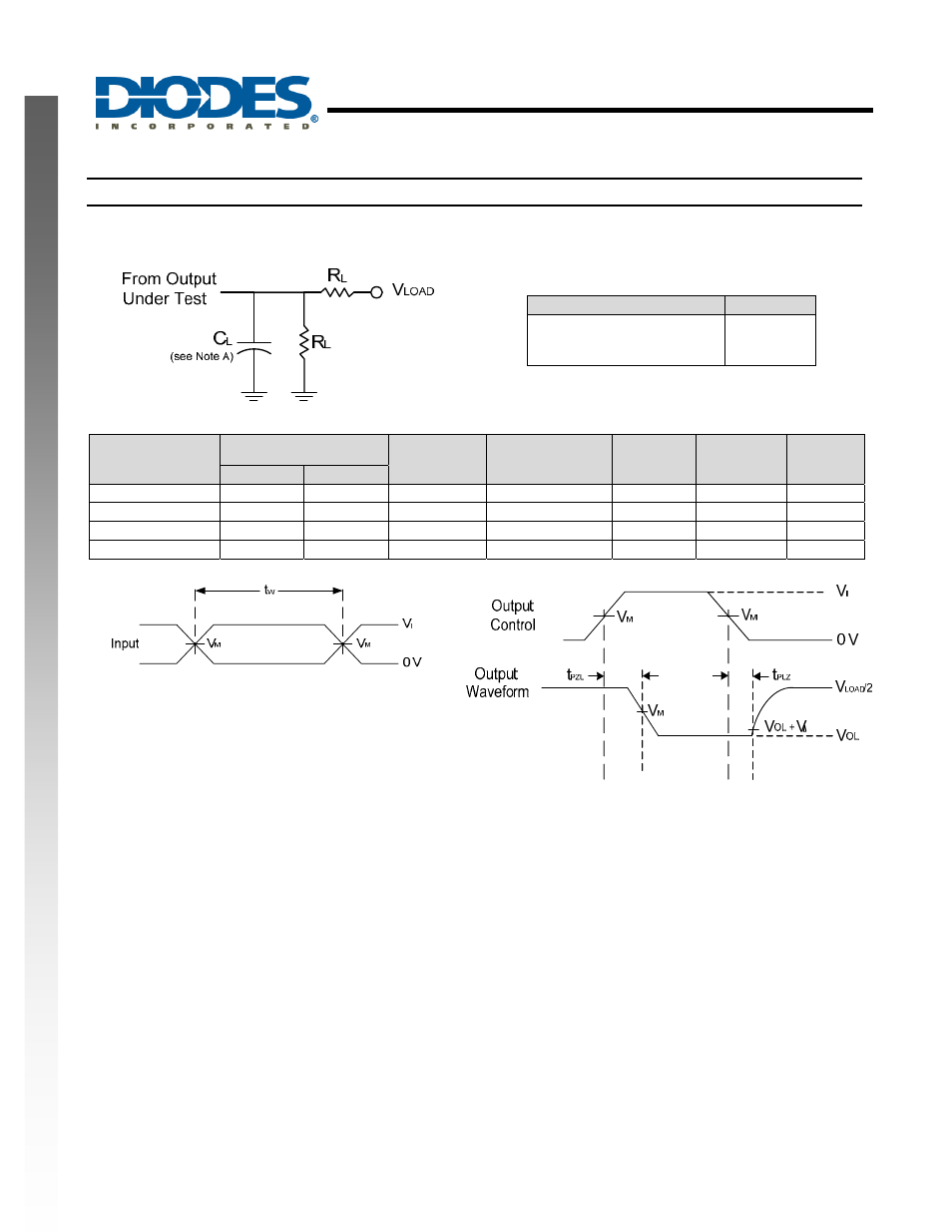
Parameter Measurement Information
Vcc
Inputs
V
M
V
LOAD
C
L
R
L
V
∆
V
I
t
r
/t
f
1.8V±0.15V V
CC
≤2ns V
CC
/2
2 X V
CC
30pF 1K
Ω 0.15V
2.5V±0.2V V
CC
≤2ns V
CC
/2
2 X V
CC
30pF
500
Ω 0.15V
3.3V±0.3V 3V
≤2.5ns 1.5V
6V
50pF 500
Ω 0.3V
5V±0.5V V
CC
≤2.5ns V
CC
/2
2 X V
CC
50pF
500
Ω 0.3V
Voltage Waveform
Pulse Duration
Voltage Waveform
Propagation Delay Times
Figure 1. Load Circuit and Voltage Waveforms
Notes: A. Includes test lead and test apparatus capacitance.
B. All pulses are supplied at pulse repetition rate
≤ 10 MHz
C. The inputs are measured one at a time with one transition per measurement.
D. For the open drain device t
PLZ
and t
PZL
are the same as t
PD
E. t
PZL
is measured at V
M
.
F. t
PLZ
is measured at V
OL
+V
∆
TEST
Condition
t
PLZ
(see Notes D and E)
t
PZL
(see Notes D and F)
Vload
Vload