Switching characteristics – Diodes 74AHC594 User Manual
Page 5
74AHC594
Document number: DS35484 Rev. 3 - 2
5 of 11
June 2013
© Diodes Incorporated
74AHC594
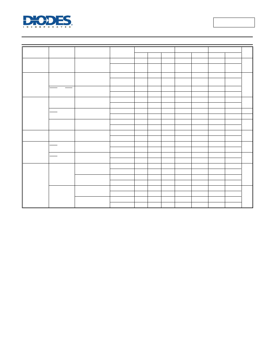
Switching Characteristics
Symbol /
Parameter
Pins
Test Conditions
V
CC
T
A
= +25°C
-40°C to +85°C
-40°C to +125°C
Unit
Min
Typ
Max Min Max Min Max
f
MAX
Maximum
Frequency
SHCP or
STCP
Figure1
3.0V to 3.6V
80
125
70
65
MHz
4.5V to 5.5V
90
70
80
70
t
W
Pulse Width
SHCP and
STCP
HIGH or LOW
Figure1
3.0V to 3.6V
6.0
6.5
7.0
ns
4.5V to 5.5V
5.5
6.0
6.5
SHR and STR
HIGH or LOW
Figure1
3.0V to 3.6V
5.0
5.0
5.5
4.5V to 5.5V
5.0
5.2
5.7
t
SU
Set-up Time
DS to SHCP
Figure1
3.0V to 3.6V
3.5
3.5
3.5
ns
4.5V to 5.5V
3.0
3.0
3.0
SHR to STCP
Figure1
3.0V to 3.6V
8.0
9.0
9.5
4.5V to 5.5V
5.0
5.0
5.5
SHCP tp
STCP
Figure1
3.0V to 3.6V
8.0
8.5
9.0
ns
4.5V to 5.5V
5.0
5.0
5.5
t
H
Hold Time
DS to SHCP
Figure1
3.0V to 3.6V
1.5
1.5
1.5
ns
4.5V to 5.5V
2.0
2.0
2.0
t
REC
Recovery Time
SHR to SHCP
Figure1
3.0V to 3.6V
4.2
4.8
5.3
ns
4.5V to 5.5V
2.9
3.3
3.8
SHR to STCP
Figure1
3.0V to 3.6V
4.6
5.3
5.8
ns
4.5V to 5.5V
3.2
3.7
4.3
t
PLH
LOW to HIGH
Propagation
Delay
SHCP toQ7S
Figure1 C
L
= 15pF
3.0V to 3.6V
5.2 8.5 2.2 9.7 2.2 10.6
ns
4.5V to 5.5V
3.8
6.3 1.7 7.2 1.7 7.8
Figure1 C
L
= 50pF
3.0V to 3.6V
7.4
11.5 3.0 13.2 3.0 14.3
4.5V to 5.5V
4.8 8.0 2.4 9.1 2.4 10.0
STCP to Qn
Figure1 C
L
= 15pF
3.0V to 3.6V
5.1 8.3 2.3 9.5 2.3 10.6
ns
4.5V to 5.5V
3.5
5.7 1.8 6.5 1.8 7.1
Figure1 C
L
= 50pF
3.0V to 3.6V
7.3
11.9 3.3 13.6 3.3 14.7
4.5V to 5.5V
4.8
7.8 2.6 9.0 2.6 9.8