Recommended operating conditions, Electrical characteristics – Diodes 74AHC594 User Manual
Page 4
74AHC594
Document number: DS35484 Rev. 3 - 2
4 of 11
June 2013
© Diodes Incorporated
74AHC594
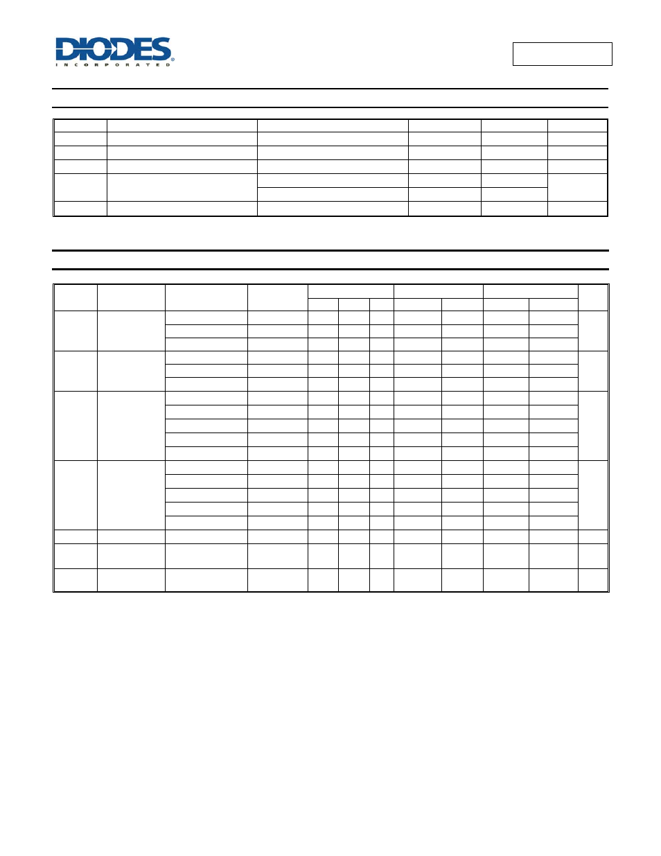
Recommended Operating Conditions
(Note 5) (@T
A
= +25°C, unless otherwise specified.)
Symbol Parameter
Conditions
Min
Max
Unit
V
CC
Supply Voltage
2.0 5.5 V
V
I
Input Voltage
0 5.5
V
V
O
Output Voltage
0
V
CC
V
Δt/ΔV
Input transition Rise or Fall Rate
V
CC
= 3.0V to 3.6V
100
ns/V
V
CC
= 4.5V to 5.5V
20
T
A
Operating Free-Air Temperature
-40 +125
°C
Note:
5. Unused inputs should be held at V
CC
or Ground.
Electrical Characteristics
(@T
A
= +25°C, unless otherwise specified.)
Symbol Parameter Test
Conditions
V
CC
T
A
= +25°C
T
A
= -40°C to +85°C
T
A
= -40°C to +125°C
Unit
Min Typ
Max
Min
Max
Min
Max
V
IH
High-Level
Input Voltage
2.0V
1.5
1.5
1.5
V
3.0V
2.1
2.1
2.1
5.5V
3.85
3.85
3.85
V
IL
Low-Level
Input Voltage
2.0V
0.5
0.5
0.5
V
3.0V
0.9
0.9
0.9
5.5V
1.65
1.65
1.65
V
OH
High-Level
Output Voltage
I
OH
= -50μA
2.0V
1.9
2.0
1.9
1.9
V
I
OH
= -50μA
3.0V 2.9
3.0
2.9
2.9
I
OH
= -50μA
4.5V 4.4
4.5
4.4
4.4
I
OH
= -4mA
3.0V 2.58
2.48
2.40
I
OH
= -8mA
4.5V 3.94
3.80
3.70
V
OL
Low-Level
Output Voltage
I
OL
= 50μA
2.0V
0
0.1
0.1
0.1
V
I
OL
= 50μA
3.0V
0
0.1
0.1
0.1
I
OL
= 50μA
4.5V
0
0.1
0.1
0.1
I
OL
= 4mA
3.0V
0.36
0.44
0.55
I
OL
= 8mA
4.5V
0.36
0.44
0.55
I
I
Input Current
V
I
= GND or 5.5V
5.5V
0.01 ±
0.1
± 1
± 2
μA
I
CC
Supply Current
V
I
= GND or V
CC
I
O
= 0
5.5V
4
40
80
μA
C
i
Input
Capacitance
V
i
= V
CC
or GND
5.5V
3.5 10
10
10 pF