Absolute maximum ratings, Electrical characteristics – Diodes AP431_A User Manual
Page 3
AP431/AP431A
Document number: DS31002 Rev. 21 - 2
3 of 17
June 2013
© Diodes Incorporated
AP431/AP431A
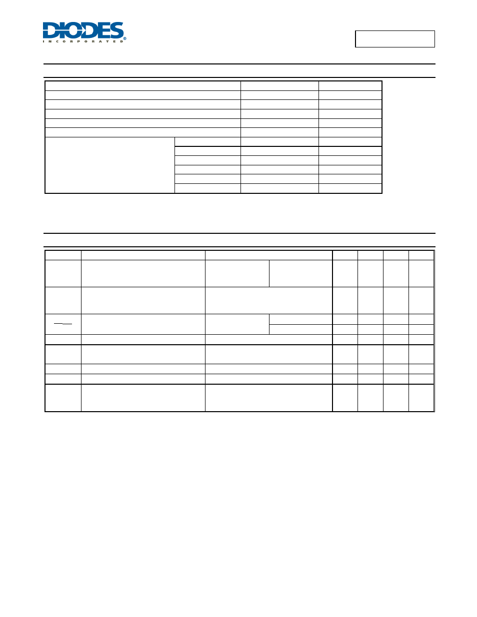
Absolute Maximum Ratings
(@T
A
= +25°C, unless otherwise specified.)
Parameter Rating
Unit
Cathode Voltage
+36
V
Continuous Cathode Current
-10 to +250
mA
Reference Input Current
10
mA
Operating Temperature
-20 to +85
°C
Storage Temperature
-65 to +150
°C
Power Dissipation (Notes 4, 5)
SOT23(R) 400
mW
SOT25 550
mW
SC59(R) 400
mW
SO-8 600
mW
SOT89 800
mW
TO92 780
mW
Notes: 4.
T
J
, max = +150°C.
5. Ratings apply to ambient temperature at +25°C.
Electrical Characteristics
(@T
A
= +25°C, V
DD
= 3V; unless otherwise specified.)
Symbol Parameter
Conditions Min
Typ
Max
Units
V
REF
Reference voltage
V
KA
= V
REF
,
I
KA
= 10mA (Figure 1)
AP431
AP431A
2.470
2.482
2.495
2.520
2.507
V
V
DEV
Deviation of reference input voltage over
temperature (Note 5)
V
KA
= V
REF
, I
KA
= 10mA
T
A
= Full Range (Figure 1)
— 8.0
20.0
mV
ΔV
REF
ΔV
KA
Ratio of the change in reference voltage to
the change in cathode voltage
I
KA
= 10mA (Figure 2)
V
KA
= V
REF
to 10V
— -1.4 -2.0
mV/V
V
KA
= 10V to 36V
— -1 -2
mV/V
I
REF
Refernce input current
R1 = 10K
Ω, R2 = ∞ I
KA
= 10mA (Figure 2)
— 1.4 3.5 µA
I
REF
Deviation of reference input current over
temperature
R1 = 10K
Ω, R2 = ∞ I
KA
= 10mA
T
A
= Full range (Figure 2)
— 0.4 1.2 µA
I
KA(MIN)
Minimum cathode current for regulation
V
KA
= V
REF
(Figure 1)
— 0.19
0.50 mA
I
KA(OFF)
Off-state current
V
KA
= 36V, V
REF
= 0V (Figure 3)
— 0.1 1.0 µA
|Z
KA
|
Dynamic output impedance (Note 7)
V
KA
= V
REF
V
KA
= V
REF
ΔI
KA
= 0.1mA to 15mA
Frequency
≤ 1KHz (Figure 1)
— 0.2 0.5
Ω