Data sheet – Diodes AM4406 User Manual
Page 9
Data Sheet
9
Nov. 2009 Rev. 1. 5
BCD Semiconductor Manufacturing Limited
2-PHASE HALF-WAVE HIGH VOLTAGE MOTOR PRE-DRIVER AM4406/4406F
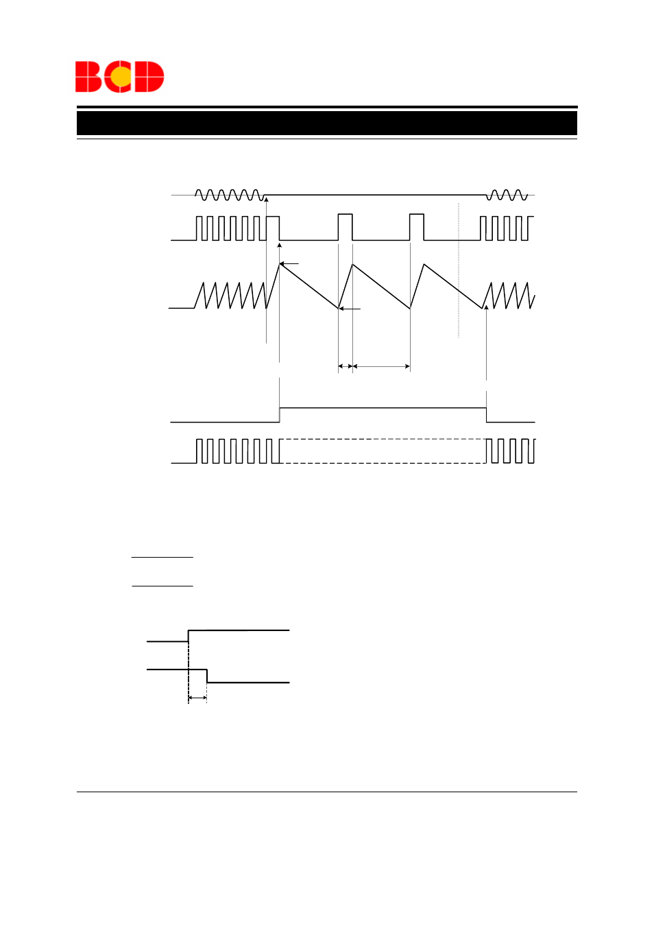
Operating Diagram
Figure 9. Control Timing Diagram of AM4406/4406F
Note 4: Automatic restart is performed in the following manner. A motor lock condition is detected when the hall signal stops
switching. The output is ON when CT pin is being charged. C2 is the external capacitor of the CT pin. Output ON time and
OFF time are determined by the capacitance of C2.
Note 5: RD pin is ON during normal operation, and OFF when the motor is locked. It is an open collector output pin.
Note 6: The RD pin may maintain HIGH level for a few hundred milliseconds when the power is turn on.
.)
(
)
(
*
Sec
I
V
V
2
C
T
CHG
CP
CL
ON
−
=
.)
(
)
(
*
Sec
I
V
V
2
C
T
DHG
CP
CL
OFF
−
=
A few hundred milliseconds
RD
Power
Reverts to normal operation
Motor Lock
Cleared
ON
OFF
Motor Locked
Motor Lock Detected
High
T
ON
T
OFF
Hall Input
Motor Output
CT
RD
FG
- PDS3200 (5 pages)
- PDS340 (5 pages)
- PDS340Q (5 pages)
- PDS360 (5 pages)
- PDS360Q (5 pages)
- PDS4150 (4 pages)
- PDS3100Q (5 pages)
- PDS3100 (5 pages)
- PDS1240CTL (5 pages)
- PDS1045 (5 pages)
- PDS1040L (5 pages)
- PDS1040CTL (5 pages)
- PDS1040 (5 pages)
- PD3S230L (5 pages)
- PD3S230H (3 pages)
- PDS5100Q (5 pages)
- PDS835L (5 pages)
- PDS760 (5 pages)
- PDS560 (5 pages)
- PDS540 (5 pages)
- PDS5100H (5 pages)
- PDS5100 (5 pages)
- PDS4200H (6 pages)
- SBL3060CTP (4 pages)
- SBL30L30CT (3 pages)
- SBL3045CTP (4 pages)
- SBL3040CTP (4 pages)
- SBL2060CTP (4 pages)
- SBL2030CT - SBL2060CT (3 pages)
- SBL2045CTP (4 pages)
- SBL1060CTP (4 pages)
- SBL1040CTP (4 pages)
- SBG3030CT - SBG3045CT (5 pages)
- SB520 - SB560 (3 pages)
- SB370 - SB3100 (3 pages)
- SB320 - SB360 (3 pages)
- SBR10U100CT (5 pages)
- SBR10U150CT (5 pages)
- SBR10A45SP5 (5 pages)
- SBR1060CT (5 pages)
- SBR1045SP5 (5 pages)
- SBR1045SD1 (4 pages)
- SBR1045D1 (5 pages)
- SBR1045CTL (4 pages)
- SBR1040CT (5 pages)