Data sheet, Ap3031 – Diodes AP3031 User Manual
Page 11
Data Sheet
11
Dec. 2012 Rev. 1. 6
BCD Semiconductor Manufacturing Limited
WHITE LED STEP-UP CONVERTER AP3031
Application Information (Continued)
changing the feedback voltage to get appropriate duty
and luminous intensity is also useful.
(1) Adding a Control Signal to CTRL Pin
Adding a PWM signal to CTRL pin directly, the
AP3031 is turned on and off by this signal. When the
PWM frequency is lower than 1kHz(Typ.), the IC
works in the soft-start mode to dimming the light. On
contrary, when the PWM frequency is higher than
1kHz(Typ.), the IC works in the standby mode: the
converter ceaselessly switches off and directly starts to
achieve light dimming. This standby function allows
AP3031 to support high frequency dimming (up to
25kHz or higher) to avoid audio noise. More details
please refer to Figure 20 and Figure 21.
Figure 20. Dimming Control
Using a PWM Signal in CTRL Pin
Figure 21. High Frequency (25kHz)
Dimming Waveform
(2) Changing the Effective Feedback Voltage
There are two popular methods to change the effective
feedback voltage.
First, adding a constant DC voltage through a resistor
divider to FB pin can control the dimming. Changing
the DC voltage or resistor between the FB Pin and the
DC voltage can get appropriate luminous intensity.
Comparing with all kinds of PWM signal control, this
method features a stable output voltage and LEDs
current. Please refer to Figure 22.
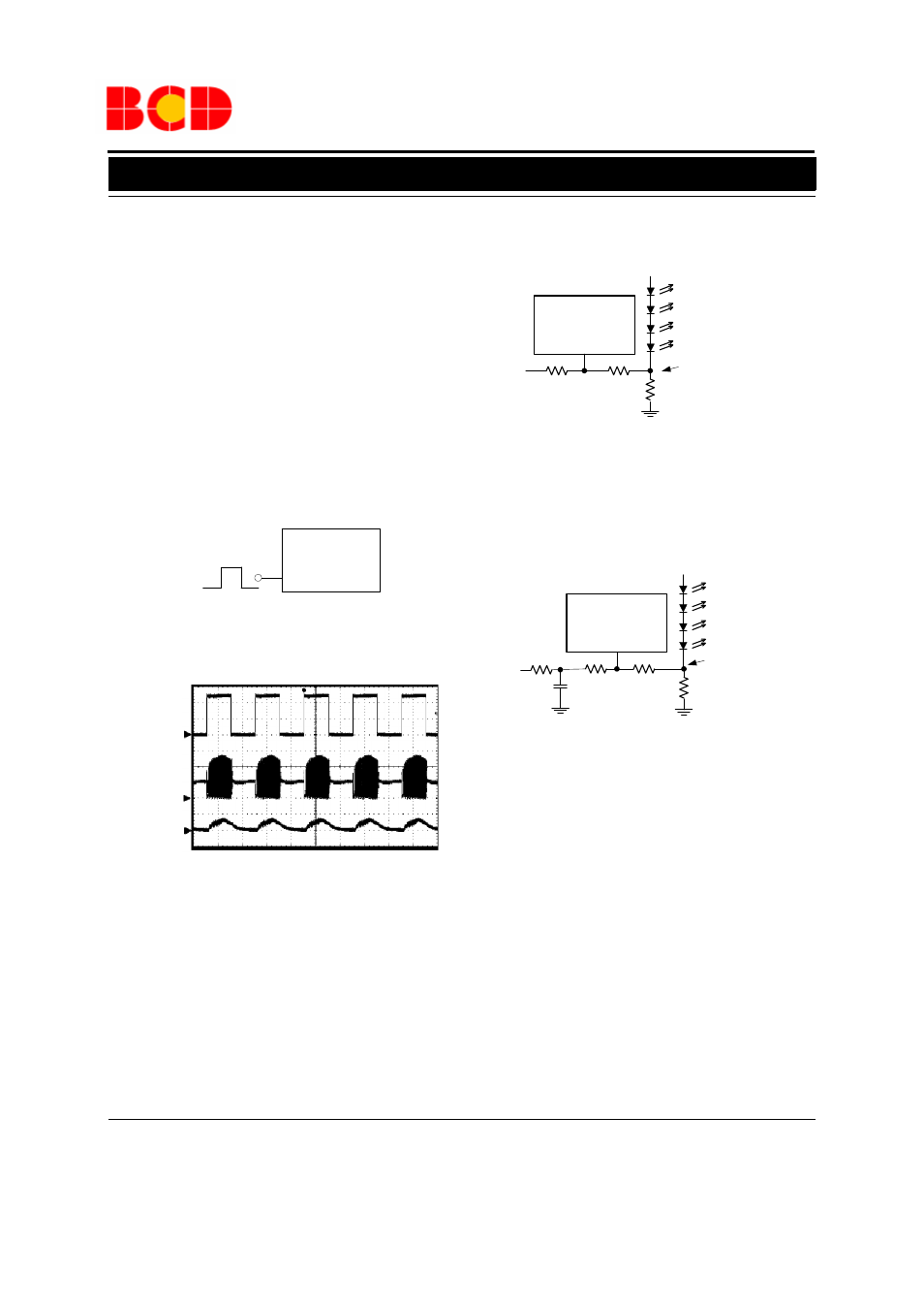
Figure 22. Dimming Control
Using DC Voltage
Second, using a filtered PWM signal can do it. The
filtered PWM signal can be considered as a varying
and adjustable DC voltage, please refer to Figure 23.
Figure 23. Dimming Control
Using Filtered PWM Voltage
V
CTRL
2.5V/div
Time 20
μs/div
V
SW
5V/div
I
L
500mA/div
R1
FB
AP3031
R2
R3
V
DC
Effective
Feedback Voltage
R1
FB
AP3031
R2
R3
PWM
R4
C
Effective
Feedback Voltage
AP3031
CTRL