Data sheet, Imv 200 r, Operation – Diodes AP3031 User Manual
Page 10: Led current control, Over voltage protection, Soft start, Standby and dimming
Data Sheet
10
Dec. 2012 Rev. 1. 6
BCD Semiconductor Manufacturing Limited
WHITE LED STEP-UP CONVERTER AP3031
Application Information
Operation
The AP3031 is a boost DC-DC converter which uses a
constant frequency, current mode control scheme to
provide excellent line and load regulation. Operation
can be best understood by referring to Figure 3 and
Figure 24.
At the start of each oscillator cycle, switch Q1 turns on.
The switch current will increase linearly. The voltage
on sense resistor is proportional to the switch current.
The output of the current sense amplifier is added to a
stabilizing ramp and the result is fed into the non-
inversion input of the PWM comparator A2. When this
voltage exceeds the output voltage level of the error
amplifier A1, the switch is turned off.
It is clear that the voltage level at inversion input of A2
sets the peak current level to keep the output in
regulation. This voltage level is the output signal of
error amplifier A1, and is the amplified signal of the
voltage difference between feedback voltage and
reference voltage of 200mV. So, a constant output
current can be provided by this operation mode.
LED Current Control
Refer to Figure 24, the LED current is controlled by the
feedback resistor R
ISET
. LEDs' current accuracy is
determined by the feedback voltage and resistor R
ISET
,
so the precise resistors are preferred. The resistance of
R
ISET
is in inverse proportion to the LED current since
the feedback reference is fixed at 200mV. The relation
for R
ISET
and LED current (I
LED
)can be expressed as
below:
Over Voltage Protection
The AP3031 has an internal open load protection
circuit. When the LEDs are disconnected from circuit
or fail open, the output voltage is clamped at about
17.5V. The AP3031 will switch at a low frequency, and
minimize current to avoid input voltage drop.
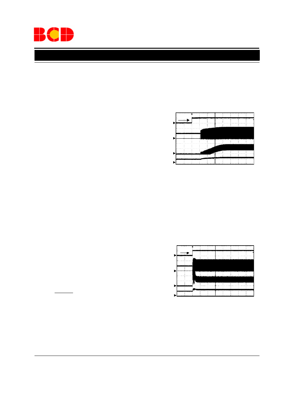
Soft Start
The AP3031 has an internal soft start circuit to limit
the inrush current during startup. If logic low time on
CTRL pin is more than about 0.7ms and then enable
the IC, the AP3031 will start smoothly to protect the
supplier. The time of startup is controlled by internal
soft-start capacitor. Details please refer to
Figure 18.
Figure 18. Soft-start Waveform
V
IN
=5V, 3
×
13 LEDs, I
LED
=260mA
Standby and Dimming
To avoid audio noise and achieve high frequency dim-
ming, AP3031 is equipped with standby function. If
logic low time on CTRL pin is less than about 0.7ms
and then enable the IC, the AP3031 will hold on
standby mode and start directly to achieve high fre-
quency dimming. Details please refer to Figure 19.
Figure 19. Standby Waveform
Two typical types of dimming control circuit are
present as below. First, controlling CTRL Pin voltage
to change operation state is a good choice. Second,
LED
ISET
I
mV
200
R
=
V
CTRL
5V/div
V
OUT
10V/div
Time 80
μs/div
V
SW
5V/div
I
L
500mA/div
V
CTRL
5V/div
V
OUT
10V/div
Time 80
μs/div
V
SW
5V/div
I
L
500mA/div
>0.7ms
<0.7ms