Ap8802h, 60v 1a led step-down converter, Preliminary new prod uc t – Diodes AP8802H User Manual
Page 6: Application information
AP8802H
60V 1A LED STEP-DOWN CONVERTER
AP8802H
Document number: DS32227 Rev. 6 - 2
6 of 14
www.diodes.com
May 2012
© Diodes Incorporated
PRELIMINARY
NEW PROD
UC
T
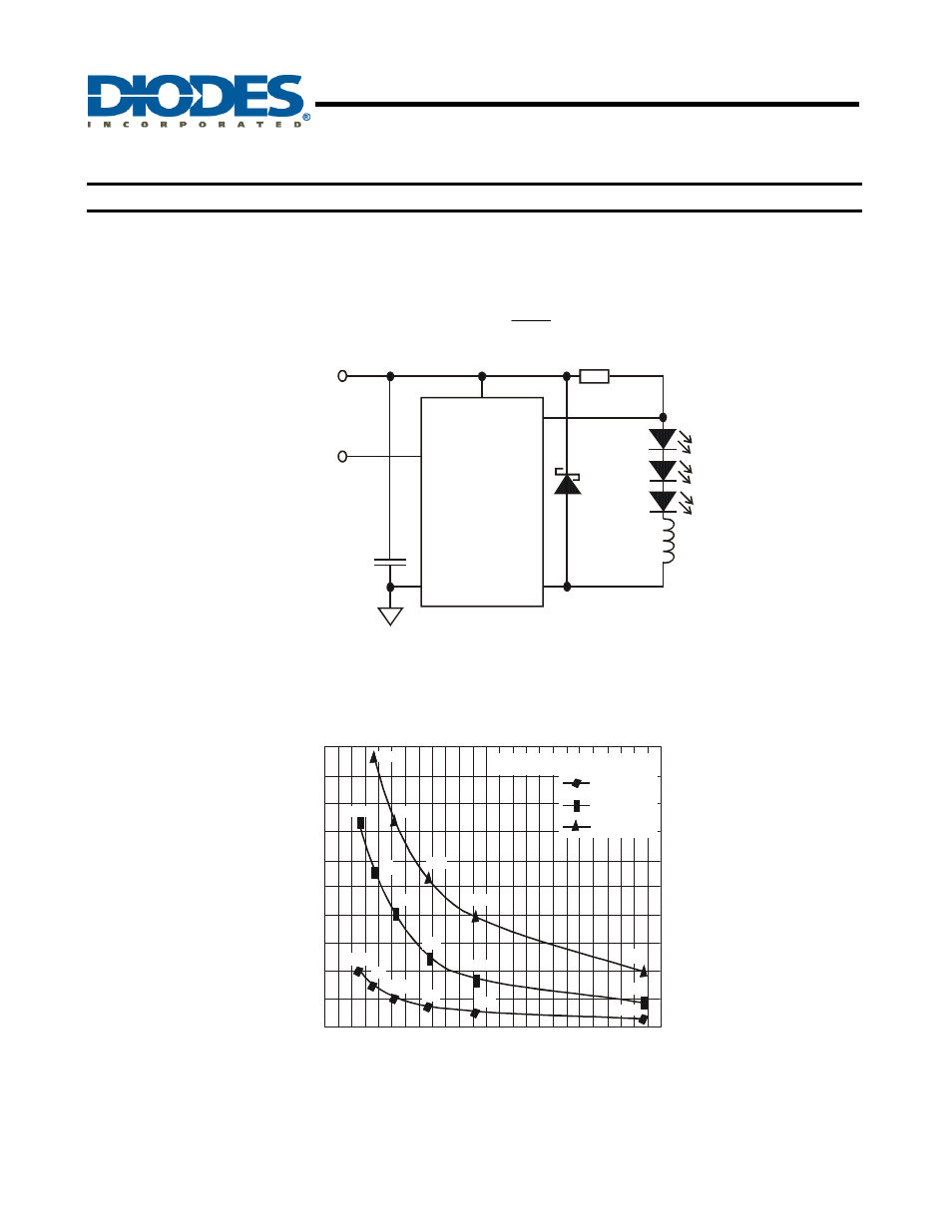
Application Information
LED Current Control
The LED current is controlled by the resistor R
SET
in Figure 14 connected between V
IN
and SET. The nominal average output current in the
LED(s) with the CTRL pin open circuit is defined as:
SET
THD
LED
R
V
I
=
48V
C1
2.2µF
L1
68µF
R
SET
0.33
Ω
D1
PDS3200
AP8802H
SW
GND
CTRL
SET
V
IN
Figure. 14 Typical Application Circuit
Inductor Selection
This section highlights how to select the inductor suitable for the application requirements in terms of switching frequency, LED current
accuracy and temperature.
INDUCTOR VALUE (µ)
Figure. 15 Switching Frequency vs. Inductor Value
0
500
50
100
150
200
250
300
350 400
450
F
R
E
Q
U
EN
C
Y
(k
H
z)
500
450
0
100
250
300
350
50
150
200
400
12V - 3 LEDs
24V - 5 LEDs
48V - 10 LEDs
Switching Frequency @I
= 700mA
LED
68
68
68
47
47
100
100
100
150
150
150
220
220
220
470
470
470
The inductor influences the LED current accuracy that the system is able to provide. The following section highlights how to select the
inductor in relation to the device packages and the LED current, while maintaining the chip temperature below +70°C.