Al8806q, Application information – Diodes AL8806Q User Manual
Page 8
AL8806Q
Document number: DS36905 Rev. 1 - 2
8 of 13
www.diodes.com
April 2014
© Diodes Incorporated
AL8806Q
Application Information
(cont.)
Analog Dimming
(cont.)
Note that 100% brightness setting corresponds to V
CTRL
= V
REF
, nominally 2.5V. For any voltage applied on the CTRL pin that is higher than V
REF
,
the device will not overdrive the LED current and will still set the current according to the equation V
CTRL
= V
REF
.
When the CTRL voltage falls below the threshold, 0.4V, the output switch is turned off which allows PWM dimming.
PWM Dimming
LED current can be adjusted digitally, by applying a low frequency Pulse Width Modulated (PWM) logic signal to the CTRL pin to turn the device on
and off. This will produce an average output current proportional to the duty cycle of the control signal. In particular, a PWM signal with a max
resolution of 10bit can be applied to the CTRL pin to change the output current to a value below the nominal average value set by resistor R
SET
. To
achieve this resolution the PWM frequency has to be lower than 500Hz, however higher dimming frequencies can be used - at the expense of
dimming dynamic range and accuracy.
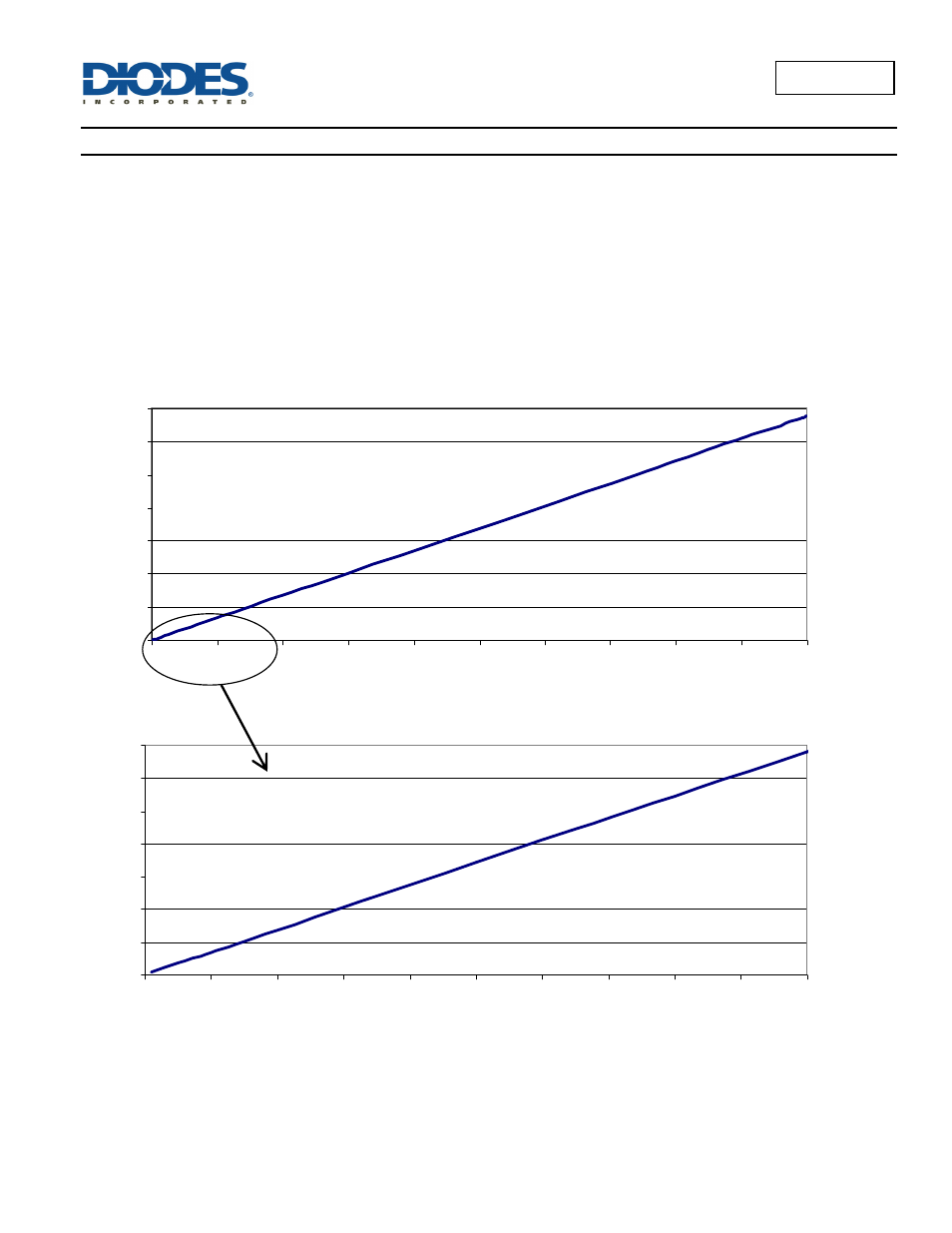
Typically, for a PWM frequency of 500Hz the accuracy is better than 1% for PWM ranging from 1% to 100%.
Figure 2 PWM Dimming at 500Hz
Figure 3 Low duty cycle PWM Dimming at 500Hz
The PWM pin is designed to be driven by both 3.3V and 5V logic levels directly from a logic output with either an open drain output or push-pull
output stage.
0
100
200
300
400
500
600
700
0%
10%
20%
30%
40%
50%
60%
70%
80%
90%
100%
PWM dimming [%]
L
E
D
c
u
rre
n
t [m
A
]
0
10
20
30
40
50
60
70
0%
1%
2%
3%
4%
5%
6%
7%
8%
9%
10%
PWM dimming [%]
LE
D
cur
rent
[
m
A
]