Al8806q, Application information – Diodes AL8806Q User Manual
Page 7
AL8806Q
Document number: DS36905 Rev. 1 - 2
7 of 13
www.diodes.com
April 2014
© Diodes Incorporated
AL8806Q
Application Information
AL8806Q Operation
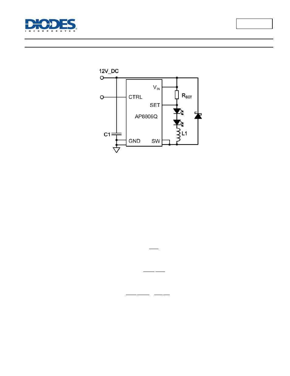
In normal operation, when voltage is applied at V
IN
, the AL8806Q internal switch is turned on. Current starts to flow through sense resistor R
SET
,
inductor L1, and the LEDs. The current ramps up linearly, and the ramp rate is determined by the input voltage V
IN
and the inductor L1.
Figure 1 Typical Application Circuit
This rising current produces a voltage ramp across R
SET
. The internal circuit of the AL8806Q senses the voltage across R
SET
and applies a
proportional voltage to the input of the internal comparator.
When this voltage reaches an internally set upper threshold, the internal switch is turned off. The inductor current continues to flow through R
SET
,
L1, the LEDs and the schottky diode D1, and back to the supply rail, but it decays, with the rate of decay determined by the forward voltage drop of
the LEDs and the schottky diode.
This decaying current produces a falling voltage at R
1
, which is sensed by the AL8806Q. A voltage proportional to the sense voltage across R
SET
is
applied at the input of the internal comparator. When this voltage falls to the internally set lower threshold, the internal switch is turned on again.
This switch-on-and-off cycle continues to provide the average LED current set by the sense resistor R
SET
.
LED Current Control
The LED current is controlled by the resistor R
SET
in Figure 1.
Connected between V
IN
and SET the nominal average output current in the LED(s) is defined as:
SET
THD
LED
R
V
I
=
If the CTRL pin is driven by an external voltage (higher than 0.4V and lower than 2.5V), the average LED current is:
SET
THD
REF
CTRL
LED
R
V
V
V
I
=
For example for a desired LED current of 1.33A and a default voltage V
CTRL
=2.5V the resulting resistor is:
Ω
≈
=
=
m
75
5
.
2
5
.
2
33
.
1
1
.
0
V
V
I
V
R
REF
CTRL
LED
THD
SET
Analog Dimming
The CTRL pin can be driven by an external DC voltage (V
CTRL
), to adjust the output current to a value below the nominal average value defined by
R
SET
. The LED current decreases linearly with the CTRL voltage when 0.5V ≤ V
CTRL
≤ 2.5V, as shown on page 4 for 4 different current levels.