Ap5727 – Diodes AP5727 User Manual
Page 7
AP5727
BIAS POWER SUPPLY FOR OLED
SUB DISPLAY AND TFT-LED
AP5727
Document number: DS31887 Rev. 2 - 2
7 of 10
www.diodes.com
January 2011
© Diodes Incorporated
NEW PROD
UC
T
Typical Performance Characteristics
(Continued)
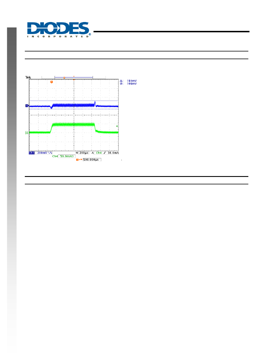
Load Transient Response
V
IN
= 3.3V; VOUT = 15V ; IOUT = 5~50mA
Application Information
Inductor Selection
A 10
μH~22μH inductor is recommended for most AP5727 applications. Although small size and high efficiency are major
concerns, the inductor should have low core loss at 1.2MHz and low DCR.
Capacitor Selection
Ceramic capacitors, due to their small size, are ideal for AP5727 applications. X5R and X7R types are recommended
because they retain their capacitance over wider voltage and temperature ranges than other types such as X5R and X7R.
A 4.7
μF input capacitor and a 10μF output capacitor are sufficient for most AP5727 applications.
Diode Selection
Schottky diodes, with their low forward voltage drop and fast reverse recovery, are the ideal choices for AP5727 applications.
The forward voltage drop of a Schottky diode represents the conduction loss in the diode, while the diode capacitance (C
T
)
represents the switching loss. For diode selection, both forward voltage drop and diode capacitance need to be considered.
Schottky diodes with higher current ratings usually have lower forward voltage drop and larger diode capacitance, which can
cause significant switching loss at the 1.2MHz switching frequency of the AP5727.
V
OUT
I
OUT