Ap5727, Bias power supply for oled sub display and tft-led, New prod uc t absolute maximum ratings – Diodes AP5727 User Manual
Page 3: Recommended operating conditions, Electrical characteristics
AP5727
BIAS POWER SUPPLY FOR OLED
SUB DISPLAY AND TFT-LED
AP5727
Document number: DS31887 Rev. 2 - 2
3 of 10
www.diodes.com
January 2011
© Diodes Incorporated
NEW PROD
UC
T
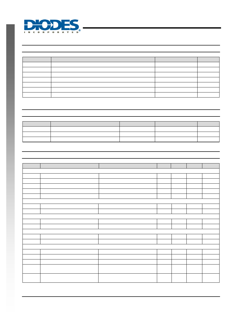
Absolute Maximum Ratings
(T
A
= 25
°C)
Symbol
Parameter
Rating
Unit
V
IN
VIN Pin Voltage
-0.3~7
V
V
SW
SW
Voltage
-0.3~32
V
V
FB
Feedback
Pin
Voltage
-0.3~7
V
EN EN
-0.3~7
V
T
J(MAX)
Maximum Junction Temperature
150
°C
T
LEAD
Lead
Temperature
300
°C
T
ST
Storage Temperature Range
-65 to +150
°C
Caution: The absolute maximum ratings are rated values exceeding which the product could suffer physical damage. These values must therefore not be
exceeded under any condition.
Recommended Operating Conditions
Symbol
Parameter
Min
Max
Unit
V
IN
Input
Voltage
2.7
5.5
V
T
J
Operating Junction Temperature
-40
125
°C
T
A
Operating Ambient Temperature
-40
85
°C
Electrical Characteristics
(V
IN
= 3.6V, T
A
= 25
°C, unless otherwise specified)
Symbol
Parameter
Conditions
Min.
Typ.
Max.
Unit
System Supply Input
V
IN
Operating Input Voltage
2.7
-
5.5
V
UVLO Under
Voltage
Lockout
-
2.2
2.4
V
Under Voltage Lockout Hysteretic
-
85
-
mV
I
Q
Quiescent Current
FB=1.3V, No Switching
-
500
-
μA
I
SD
Shutdown
Current
V
EN
< 0.4V
-
0.1
1
μA
Oscillator
F
OSC
Operation
Frequency
1
1.2
1.4
MHz
Dmax
Maximum Duty Cycle
86
90
-
%
Reference Voltage
V
FB
Feedback
Voltage
1.225 1.25 1.275
V
I
FB
FB Pin Bias Current
10
45
100
nA
MOSFET
R
DS(on)
On Resistance of MOSFET
-
0.95
1.2
Ω
I
OCP
Switching Current Limit
Normal Operation
-
750
-
mA
Control and Protection
EN Voltage
High
ON
1.5
-
-
V
EN Voltage
Low
OFF
-
-
0.4
V
I
EN
EN Pin Pull Low Current
-
4
6
μA
θ
JA
Thermal Resistance Junction-to-
Ambient
SOT25 (Note 2)
162
o
C/W
θ
JC
Thermal Resistance Junction-to-
Case
SOT25 (Note 2)
36
o
C/W
Notes: 2. Test condition for SOT25: Device mounted on FR-4 substrate, single-layer PC board, 2oz copper, with minimum recommended pad layout