Ap5724, Applications information, Ap5724 fb r – Diodes AP5724 User Manual
Page 9: Logic signal
AP5724
Document number: DS31843 Rev. 4 - 2
9 of 15
December 2013
© Diodes Incorporated
AP5724
Applications Information
(cont.)
Dimming Control
There are four different types of dimming control circuits:
1. Using a PWM Signal to EN Pin
With the PWM signal applied to the EN pin, the AP5724 is turned on or off by the PWM signal. The LEDs operate at either zero or full current. The
average LED current increases proportionally with the duty cycle of the PWM signal. A 0% duty cycle will turn off the AP5724 and corresponds to
zero LED current. A 100% duty cycle corresponds to full current. The typical frequency range of the PWM signal is below 2 kHz.
2. Using a DC Voltage
For some applications, the preferred method of brightness control is a variable DC voltage to adjust the LED current. The dimming control using a
DC voltage is shown in Figure 3. As the DC voltage increases, the voltage drop on R2 increases and the voltage drop on R
SET
decreases. Thus,
the LED current decreases. The selection of R2 and R3 will make the current from the variable DC source much smaller than the LED current and
much larger than the FB pin bias current. For V
DC
range from 0V to 2V, the selection of resistors in Figure 3 gives dimming control of LED current
from 0mA to 20mA.
AP5724
FB
R
SET
5
R2
5k
R3
100k
V
DC
Figure 3 Dimming Control Using a DC Voltage
3. Using a Filtered PWM Signal
The filtered PWM signal can be considered as an adjustable DC voltage. It can be used to replace the variable DC voltage source in dimming
control.
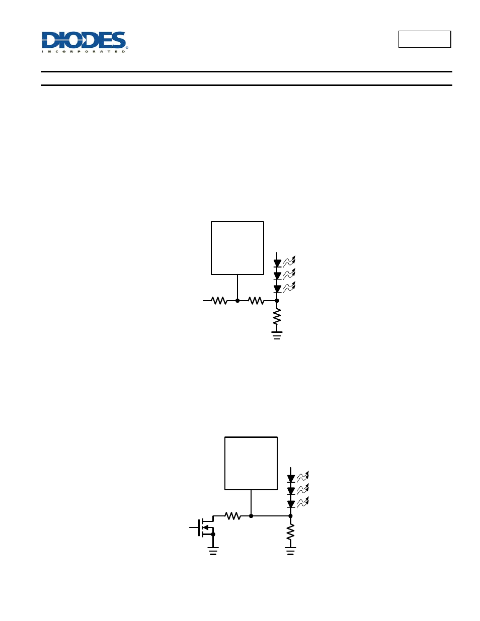
4. Using a Logic Signal
For applications that need to adjust the LED current in discrete steps, a logic signal can be used as shown in Figure 4. R
SET
sets the minimum LED
current (when the NMOS is off). R
SET
sets how much the LED current increases when the NMOS is turned on.
AP5724
FB
R
SET
R
INC
Logic
Signal
Figure 4
Dimming Control Using a Logic Signal