Ap1690, Electrical characteristics – Diodes AP1690 User Manual
Page 4
AP1690
Document number: DS36469 Rev.
2 - 2
4 of 9
May 2014
© Diodes Incorporated
AP1690
A Product Line of
Diodes Incorporated
N
E
W
P
R
O
D
U
C
T
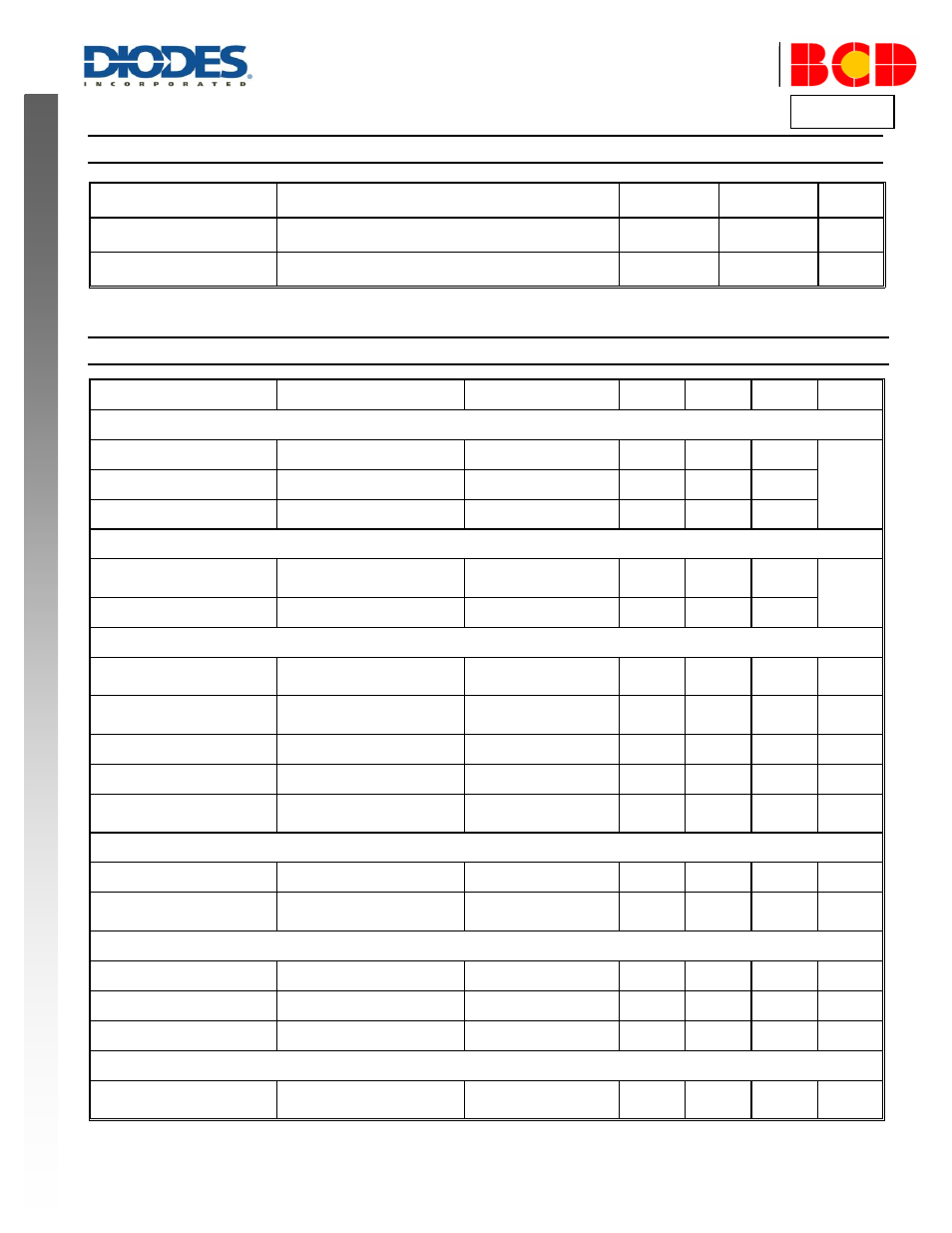
Recommended Operating Conditions
Symbol
Parameter
Min
Max
Unit
V
CC
Power Supply Voltage
9
21
V
T
A
Ambient Temperature
-40
+105
ºC
Electrical Characteristics
(@V
CC
= 15V, T
A
= +25°C, unless otherwise specified.)
Symbol
Parameter
Conditions
Min
Typ
Max
Unit
UVLO Section
V
TH
(ST)
Start-up Threshold
–
18
19
20
V
V
OPR
(Min)
Minimal Operating Voltage
After turn on
7
8
9
V
CC_OVP
VCC OVP Voltage
–
28
32
36
Standby Current Section
I
ST
Start-up Current
V
CC
= V
TH
(ST)-0.5V,
Before start up
–
–
100
µA
I
CC
(Max)
Maximum Operating Current
V
PD
= V
DIM
= 3V
–
1500
2000
Drive Output Section
V
OH
Output High Level Voltage
I
GD-SOURCE
= 20mA
V
CC
= 12V
10
–
–
V
V
OL
Output Low Level Voltage
I
GD-SINK
= 20mA
V
CC
= 12V
–
–
1
V
t
R
Output Voltage Rise Time
C
L
= 1nF
100
140
190
ns
t
F
Output Voltage Fall Time
C
L
= 1nF
30
60
90
ns
V
O-CLAMP
Output Clamp Voltage
I
GD-SOURCE
= 5mA
V
CC
= 20V
12
13.5
15
V
Current Sense Section
t
ON
(Min)
Minimum On Time
–
500
750
1000
ns
V
SOCP
Short Circuit Protection
Voltage
–
3
4
–
V
Feedback Input Section
I
FB
FB Pin Input Leakage Current
V
FB
= 4V
–
2
8
µA
V
FB
(ACC)
Acceleration Start Threshold
–
1.4
1.8
2.2
V
V
FB
(OVP)
Over Voltage Protection
–
4.5
6
7.5
V
Dimming Section
V
IN
PD Pin and DIM Pin Input
Voltage Range
–
–
3
6
V