Preliminary datasheet, Low-power off-line psr led controller ap1686, Pin configuration – Diodes AP1686 User Manual
Page 2: Pin description
Preliminary Datasheet
Low-Power Off-line PSR LED Controller AP1686
Nov. 2012 Rev. 1.1 BCD Semiconductor Manufacturing Limited
2
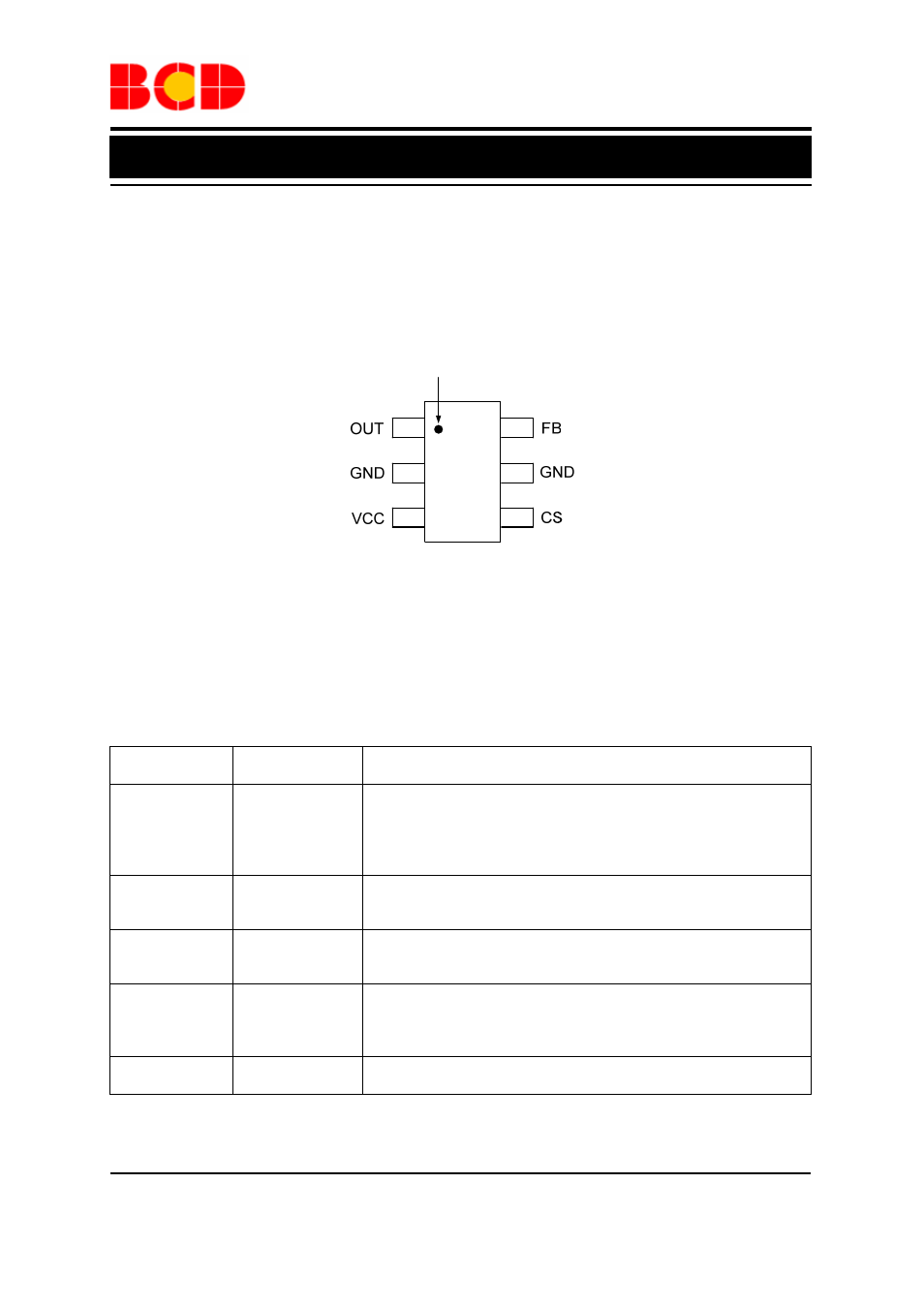
Pin Configuration
K6 Package
(SOT-23-6)
1
2
3
4
5
Pin 1 Mark
6
Figure 2. Pin Configuration of AP1686 (Top View)
Pin Description
Pin Number
Pin Name
Function
1 OUT
The OUT pin is used to turn on and turn off the power switch. When
turning on the power switch, the OUT pin will output 30mA source
current to support the base current of the power BJT. When turning
off the power switch, the resistance between the OUT and GND will
become to 5
Ω
2, 5
GND
The GND pin is the ground of the IC. When the power BJT is turned
off, a fast reverse sinking current to the gate of BJT will flow out
from this pin. Attention should be paid to in the PCB layout
3 VCC
The VCC pin supplies the power for the IC. In order to get the
correct operation of the IC, a capacitor with low ESR should be
placed as close as possible to the VCC pin
4 CS
The CS is the current sense pin of the IC. The IC will turn off the
power BJT according to the voltage on the CS pin. When the power
BJT is on, a current is output from the CS pin which is proportional
to the line voltage to realize the function of line compensation
6 FB
The CV and CC regulation are realized based on the voltage
sampling of this pin