Typical applications circuit, Pin descriptions, Ap7361 – Diodes AP7361 User Manual
Page 2
AP7361
Document number: DS33626 Rev. 9 - 2
2 of 22
October 2013
© Diodes Incorporated
AP7361
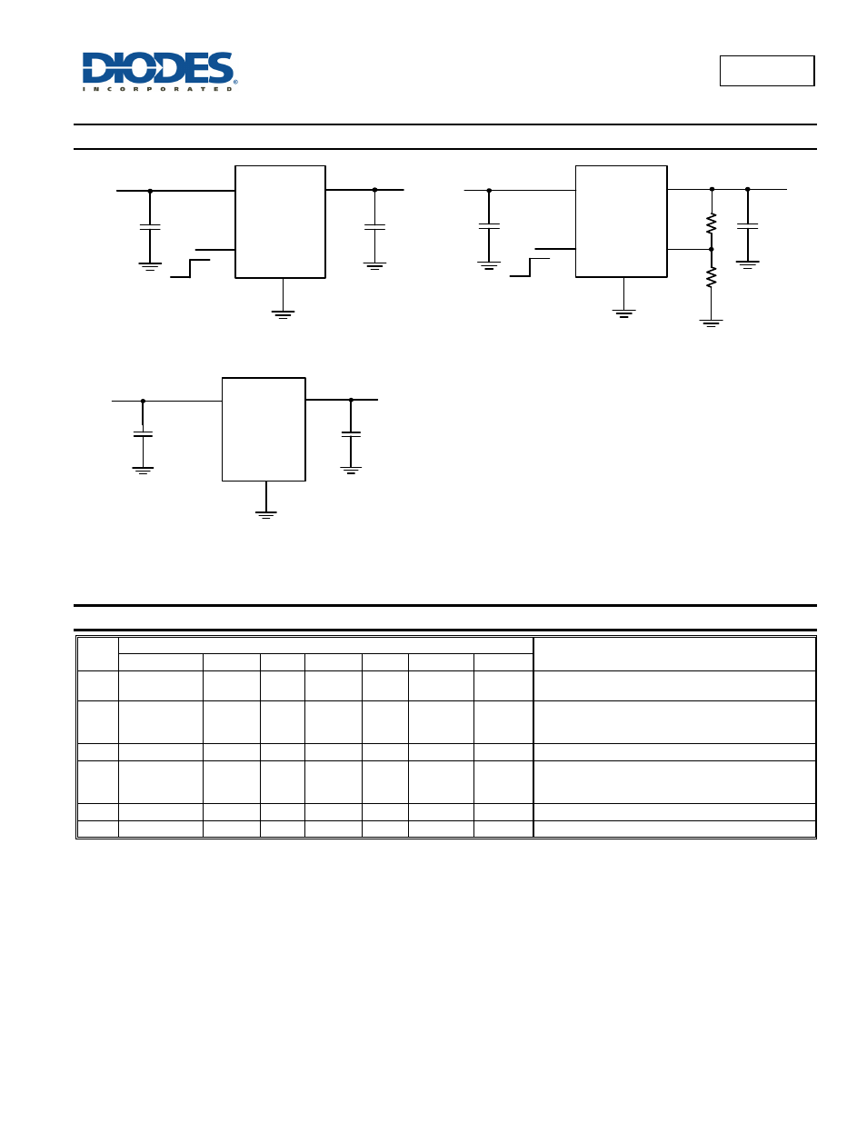
Typical Applications Circuit
4.7uF
Fixed Version
U-DFN3030-8, SOT89-5 and SO-8EP
1uF
IN
GND
EN
OUT
Enable
V
IN
V
OUT
AP7361
4.7uF
Fixed Version
TO252, SOT223
1uF
IN
GND
OUT
V
IN
V
OUT
AP7361
1uF
IN
GND
EN
OUT
Enable
ADJ
R2
R1
4.7uF
V
IN
V
OUT
AP7361
Adjustable Output
U-DFN3030-8 and SOT89-5
Pin Descriptions
Pin
Name
Pin Number
Function
U-DFN3030-8 SOT89-5 TO252 TO252R SOT223 SOT223R SO-8EP
IN 8
4 1 3 1 3 8
The input of the regulator. Bypass to ground through at
least 1µF ceramic capacitor.
OUT 1
5 3 2 3 2 1
The output of the regulator. Bypass to ground through
at least 2.2µF ceramic capacitor. For improved ac load
response a larger capacitor is recommended.
GND 4
2 2 1 2 1 4
Ground.
ADJ 3
3
NA
NA
NA
NA NA
Adjustable voltage version only – a resistor divider from
this pin to the OUT pin and ground sets the output
voltage.
EN
5
1
NA
NA
NA
NA
2
Enable input, active high.
NC
2, 6, 7
NA
NA
NA
NA
NA
3, 5, 6, 7 No connection.