Functional block diagram, Typical application circuit, 1a dual channel current-limited power switch – Diodes AP2172 User Manual
Page 3
AP2162/AP2172
1A DUAL CHANNEL CURRENT-LIMITED POWER
SWITCH
AP2162/AP2172 Rev. 5
3 of 17
FEBRUARY 2009
©
Diodes Incorporated
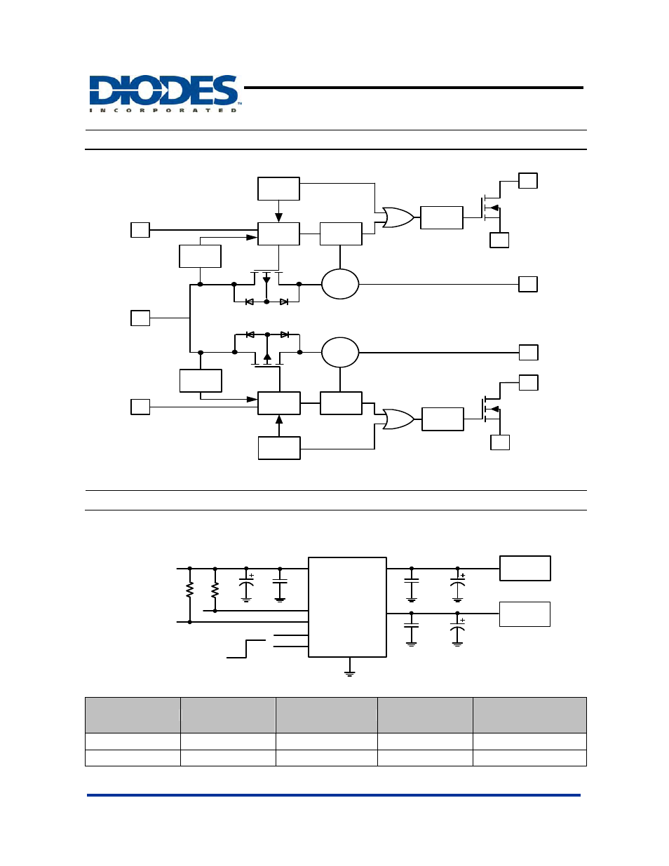
Functional Block Diagram
T h e rm a l
S e n se
D rive r
F L G 2
O U T 2
G N D
IN
E N 2
U V L O
C u rre n t
L im it
D e g litch
T h e rm a l
S e n s e
D rive r
U V L O
C u rre n t
L im it
D e g litch
O U T 1
F L G 1
E N 1
G N D
C u rre n t
S e n se
C u rre n t
S e n se
A P 2 1 6 2 , A P 2 1 7 2
0.1uF
IN
GND
EN2
OUT1
ON
68uF
Power Supply
2.7V to 5.5V
0.1uF
OFF
FLG1
Load
10k
10k
FLG2
EN1
OUT2
68uF
0.1uF
Load
10uF
AP2172 Enable Active High
Available Options
Part Number
Channel
Enable Pin (EN)
Current Limit
(Typical)
Recommended
Maximum Continuous
Load Current
AP2162 2 Active
Low
1.5A 1.0A
AP2172 2 Active
High
1.5A 1.0A
Typical Application Circuit
This manual is related to the following products: